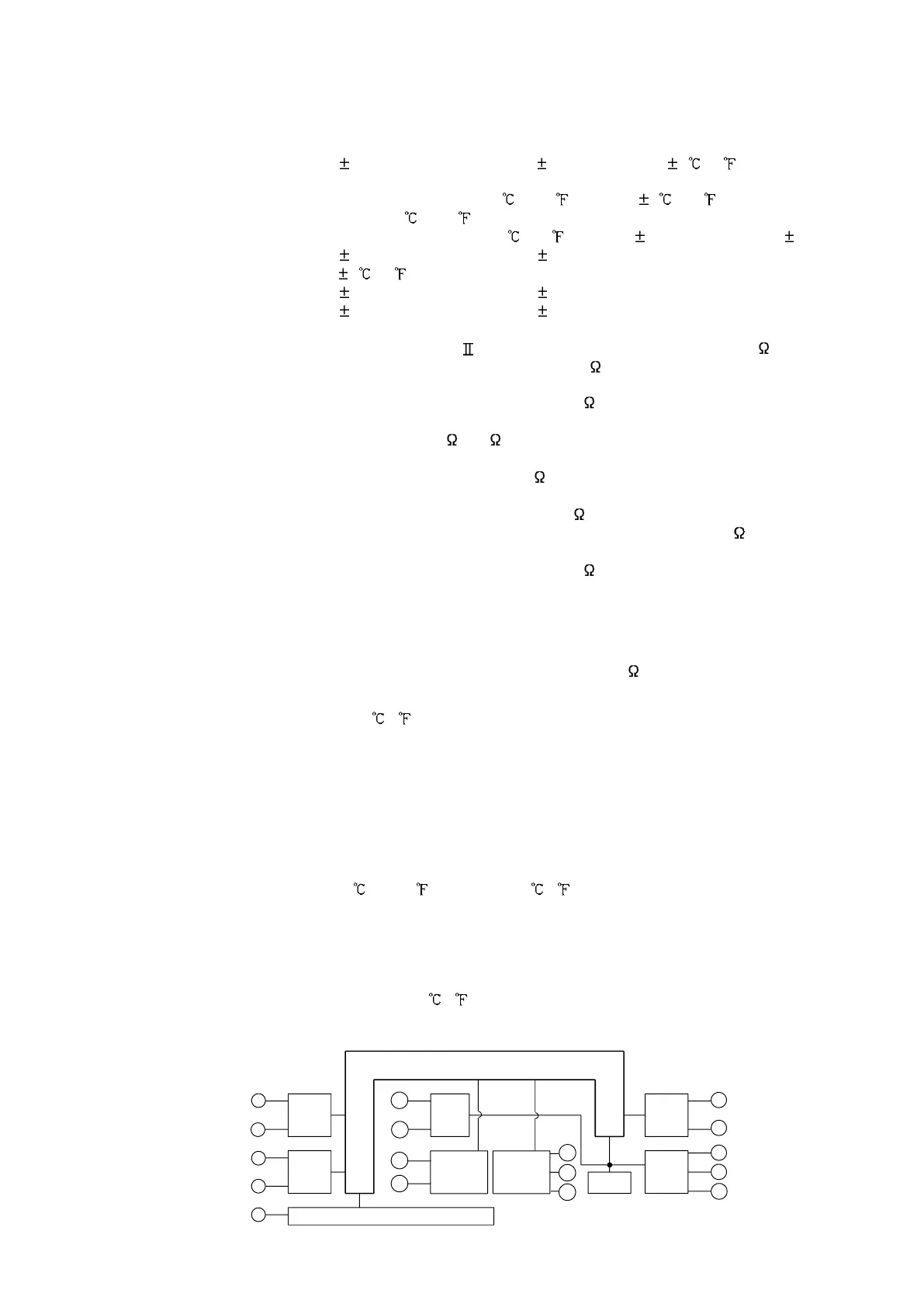
14
r
Insulated
Power
supply
A
1
CPU
CT
input
OUT1
Input
EVT (A2, LA, W)
or OUT2
(
DT
)
15
5
4
3
9
8
1
2
12
7
6
11
10
14
SV2
Commu-
nication
14
13
13
9. Specifications
9.1 Standard specifications
Mounting : Flush
Setting : Input system using membrane sheet key
Display PV display : Red LED 4 digits, character size 10.2 x 4.9 mm (H x W)
SV display : Green LED 4 digits, character size 8.8 x 4.9 mm (H x W)
Accuracy (Setting and Indication):
Thermocouple : Within 0.2% of each input span 1digit, or within 2 (4 ),
whichever is greater
However R, S inputs, 0 to 200 (400 ): Within 6 (12 )
B input, 0 to 300 (600 ): Accuracy is not guaranteed.
K, J, E, T, N inputs, less than 0 (32 ): Within 0.4% of input span 1digit
RTD : Within 0.1% of each input span 1digit, or
within 1 (2 ), whichever is greater
DC current : Within 0.2% of each input span 1digit
DC voltage : Within 0.2% of each input span 1digit
Input sampling period : 0.25 seconds
Input Thermocouple : K, J, R, S, B, E, T, N, PL- , C(W/Re5-26) External resistance, 100 or less
(However, B input: External resistance, 40 or less)
RTD : Pt100, JPt100, 3-wire system
Allowable input lead wire resistance (10 or less per wire)
DC current : 0 to 20mA DC, 4 to 20mA DC
Input impedance: 50 [50 shunt resistor (sold separately) must be
installed between input terminals.] Allowable input current, 50mA or less
DC voltage : 0 to 1V DC Input impedance (1M or more)
Allowable input voltage (5V DC or less)
Allowable signal source resistance (2k or less)
: 0 to 5V DC, 1 to 5V DC, 0 to 10V DC Input impedance (100k or more)
Allowable input voltage (15V DC or less)
Allowable signal source resistance (100 or less)
OUT1 output
Relay contact : 1a, Control capacity 3A 250V AC (resistive load)
1A 250V AC (inductive load cosø=0.4)
Electrical life, 100,000 times
Non-contact voltage (For SSR drive): 12
+2
0
V DC, maximum 40mA (short circuit protected)
DC current : 4 to 20mA DC, Load resistance, maximum 550
A1 output
Action : ON/OFF action
Hysteresis : 0.1 to 100.0 ( ), or 1 to 1000
Output : Relay contact 1a
Control capacity, 3A 250V AC (resistive load)
Electrical life, 100,000 times
Control action
PID action (with auto-tuning function)
PI action: When derivative time is set to 0
PD action (with auto reset function): When integral time is set to 0
P action (with auto reset function): When derivative and integral times are set to 0.
ON/OFF action: When proportional band is set to 0 or 0.0
OUT1 proportional band : 0 to 1000 (2000 ), 0.0 to 999.9 ( ) or 0.0 to 100.0%
(ON/OFF action when set to 0 or 0.0)
Integral time : 0 to 1000sec (OFF when set to 0)
Derivative time : 0 to 300sec (OFF when set to 0)
OUT1 proportional cycle : 1 to 120sec (Not available for DC current output type)
ARW : 0 to 100%
OUT1 ON/OFF action hysteresis: 0.1 to 100.0 ( ), or 1 to 1000
OUT1 high limit setting : 0 to 100% (DC current output type: –5 to 105%)
OUT1 low limit setting : 0 to 100% (DC current output type: –5 to 105%)
Circuit insulation configuration
When OUT1 is non-contact voltage output or DC current output, OUT1 is not insulated from Communication,
and OUT1 is not insulated from SV2. So an insulation test must not be carried out between them.

 Loading...


