11
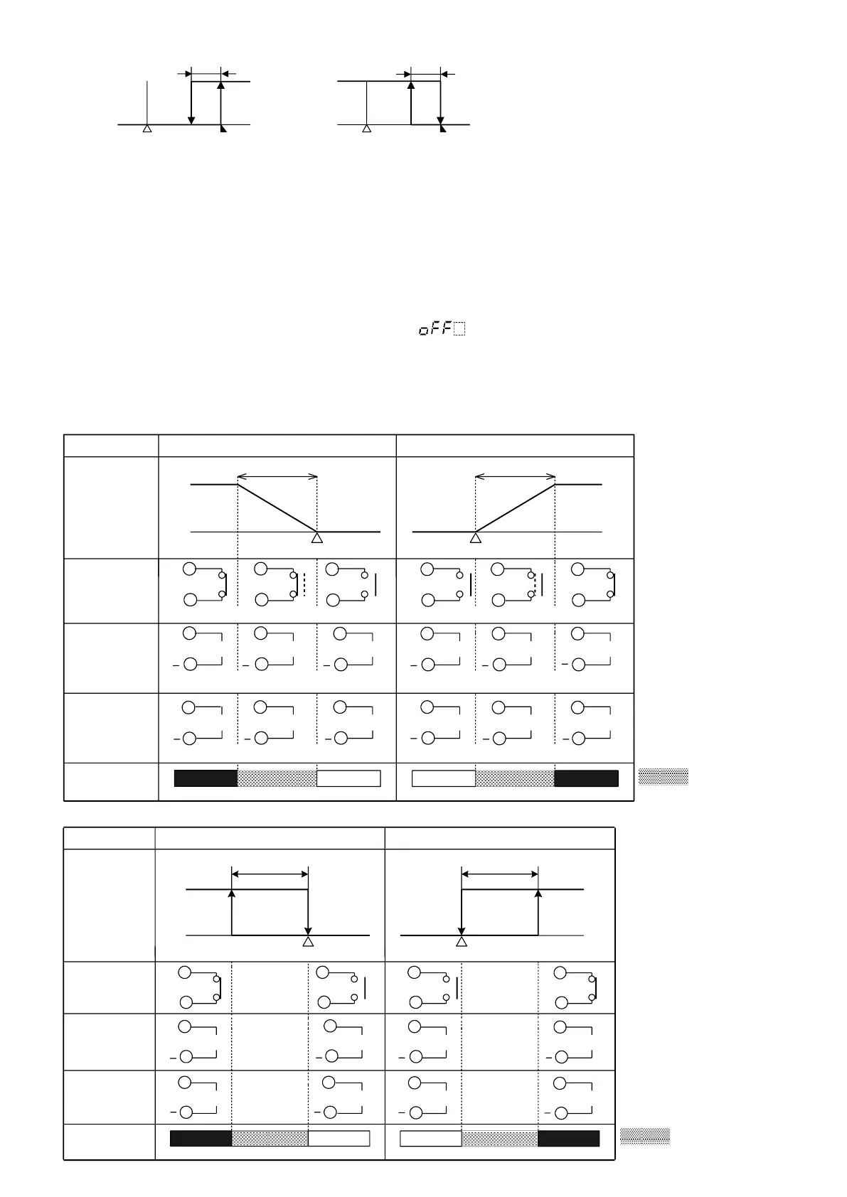
Heating ( Reverse) action Cooling (Direct) action
Control
action
Relay contact
output
Non- contact
voltage output
DC current
output
Indicator
(OUT1) Green
0
V DC
12
V DC
+
4
mA DC
Lit
Unlit
ON
OFF
SV
ON
OFF
Hysteresis Hysteresis
0
V DC
12
V DC
4
mA DC
20
mA DC
UnlitLit
20
mA DC
+
+ +
+
+
+
+
7
6
7
6
7
6
7
6
7
6
7
6
7
6
7
6
7
6
7
6
7
6
7
6
SV
Heating (Reverse ) action Cooling (Direct ) action
Control
action
Cycle action is performed according to deviation
Relay contact
output
Non- contact
voltage output
Changes continuously according to deviation
DC current
output
Indicator
(OUT1) Green
Lit
Unlit
ON
OFF
SV
Proportional band
ON
OFF
0
V DC
0/12
V DC
12
V DC
+
20
mA DC
20
to
4
mA DC
4
to
20
mA DC
Proportional band
Lit
0
V DC
12
V DC
12/0
V DC
20
mA DC
4
mA DC
Changes continuously according to deviation
+ +
+ +
+
+
+
+
++
+
Unlit
4
mA DC
7
6
7
6
7
6
7
6
7
6
7
6
7
6
7
6
7
6
7
6
7
6
7
6
7
6
7
6
7
6
7
6
7
6
7
6
SV
Cycle action is performed according to deviation
Cycle action is performed according to deviation
Cycle action is performed according to deviation
: Acts ON (lit) or
OFF (unlit).
: Acts ON (lit) or
OFF (unlit).
OFF
ON
A1 hysteresis
SV
+A1 value
OFF
ON
SV
A1 hysteresis
+A1 value
High limit alarm (when Energized is set) High limit alarm (when Deenergized is set)
(Fig. 5.5-1) (Fig. 5.5-2)
6. Operation
After the unit is mounted to the control panel and wiring is completed, operate the unit following the procedures below.
(1) Switch power supply to the JCS-33A ON.
• For approx. 3sec after the power is switched ON, the sensor input characters and the temperature unit
are indicated on the PV display, and input range high limit value is indicated on the SV display.
(For DC current and voltage input, scaling high limit value is indicated.) See (Table 5.1-1).
During this time, all outputs and LED indicators are in OFF status.
• After that, control starts indicating PV (process variable) on the PV display, and SV (desired value) on the SV
display.
• While the Control output OFF function is working, is indicated on the PV display.
(2) Input each set value. Refer to “5. Operation”.
(3) Turn the load circuit power ON.
Control action starts so as to keep the control target at the SV (desired value).
7. Action explanation
7.1 OUT1 action
7.2 OUT1 ON/OFF action

 Loading...


