4
4. Wiring
Warning
Turn the power supply to the instrument off before wiring or checking.
Working or touching the terminal with the power switched on may result in severe injury or death
due to Electric Shock.
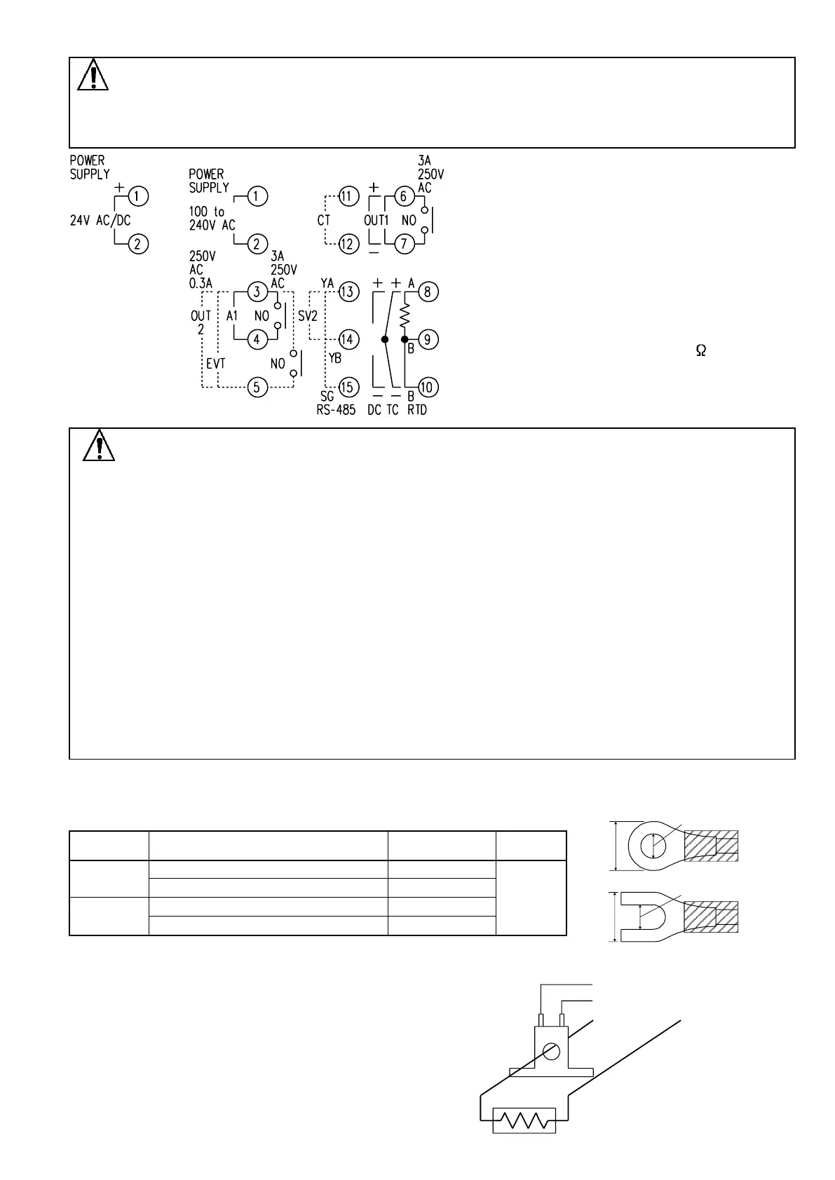
• OUT1 : Control output 1
• OUT2 : Control output 2
• A1 : Alarm 1 output
• EVT : Event output (A2 output, Heater burnout
alarm output, Loop break alarm output)
• CT : CT input
• SV2 : SV1/SV2 external selection
• RS-485 : Serial communication (RS-485)
• TC : Thermocouple input
• RTD : Resistance temperature detector input
• DC : DC current, DC voltage input
For DC current input, 50 shunt
resistor must be connected
between input terminals.
Notice
• The terminal block of the JCS-33A is designed to be wired from the left side.
The lead wire must be inserted from the left side of the terminal, and fastened by the terminal screw.
• Dotted lines show options.
• Use a thermocouple and compensating lead wire that correspond to the sensor input specification of
this controller.
• Use the 3-wire RTD which corresponds to the input specification of this controller.
• This controller does not have a built-in power switch, circuit breaker or fuse. Therefore, it is necessary
to install them in the circuit near the external controller.
(Recommended fuse: Time-lag fuse, rated voltage 250V AC, rated current 2A)
• For a 24V AC/DC power source, do not confuse polarity when using direct current (DC).
• When using a relay contact output type, externally use a relay according to the capacity of the load to
protect the built-in relay contact.
• When wiring, keep input wires (thermocouple, RTD, etc.) away from AC sources or load wires to avoid
external interference.
• Do not apply a commercial power source to the sensor connected to the input terminal nor allow the
power source to come into contact with the sensor.
Lead wire solderless terminal
Use a solderless terminal with an insulation sleeve in which an M3 screw fits as shown below.
The torque should be approximately 0.63N•m.
Nichifu Terminal Industries CO.,LTD.
Japan Solderless Terminal MFG CO.,LTD.
Nichifu Terminal Industries CO.,LTD.
Japan Solderless Terminal MFG CO.,LTD.
Heater burnout alarm option
(1) This alarm is not usable for detecting heater current
under phase control.
(2) Use the current transformer (CT) provided, and pass one
lead wire of the heater circuit into the hole of the CT.
(3) When wiring, keep the CT wire away from AC sources
or load wires to avoid external interference. (Fig. 4-3)
CT input terminal
Power
supply
Heater
CT
(11)
(12)
 Loading...


