Shure Incorporated
13/16
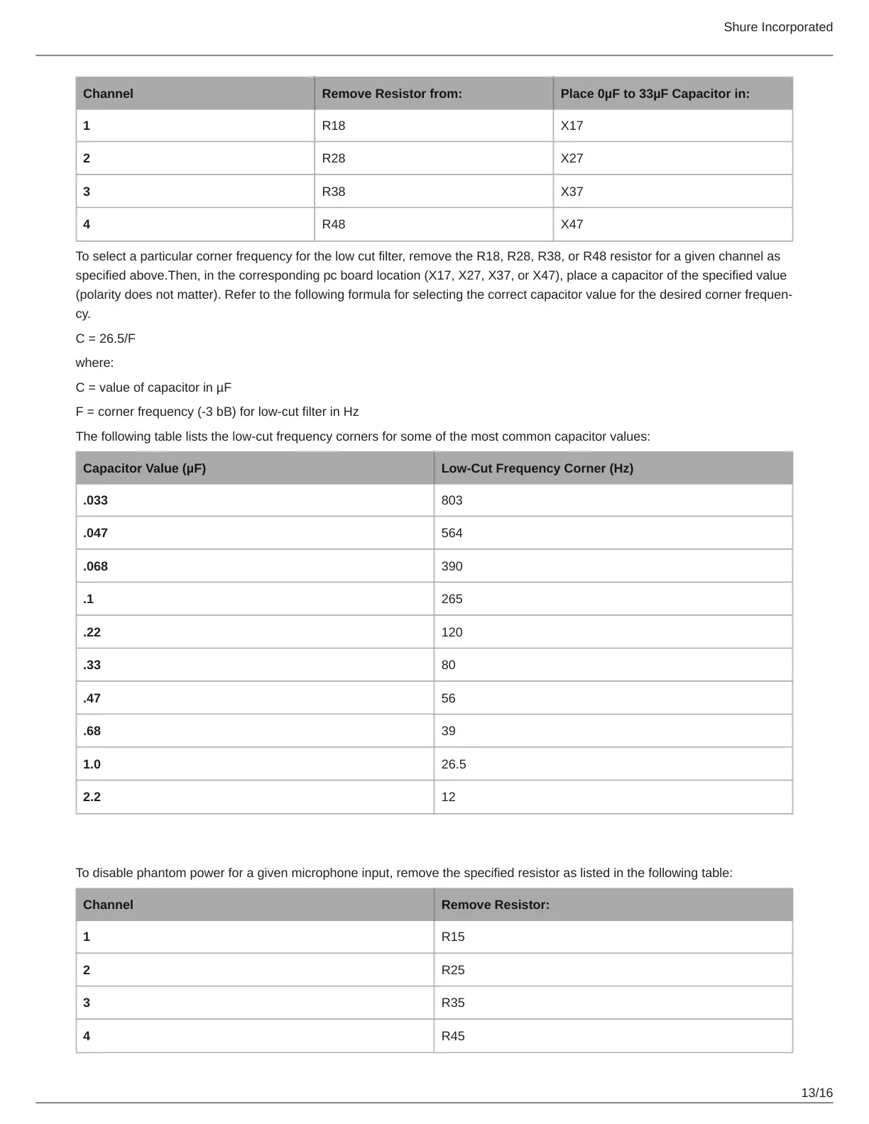
Channel Remove Resistor from: Place 0µF to 33µF Capacitor in:
1 R18 X17
2 R28 X27
3 R38 X37
4 R48 X47
To select a particular corner frequency for the low cut filter, remove the R18, R28, R38, or R48 resistor for a given channel as
specified above.Then, in the corresponding pc board location (X17, X27, X37, or X47), place a capacitor of the specified value
(polarity does not matter). Refer to the following formula for selecting the correct capacitor value for the desired corner frequen
cy.
C = 26.5/F
where:
C = value of capacitor in µF
F = corner frequency (-3 bB) for low-cut filter in Hz
The following table lists the low-cut frequency corners for some of the most common capacitor values:
Capacitor Value (µF) Low-Cut Frequency Corner (Hz)
.033 803
.047 564
.068 390
.1 265
.22 120
.33 80
.47 56
.68 39
1.0 26.5
2.2 12
Phantom Power Disable
To disable phantom power for a given microphone input, remove the specified resistor as listed in the following table:
Channel Remove Resistor:
1 R15
2 R25
3 R35
4 R45