Shure Incorporated
14/16
1.
2.
Line Pad
To insert a 50 dB line pad for a given microphone input, remove the specified resistor and short the solder points at the speci
fied pc board locations. Refer to the following table:
Channel Remove Resistors: Short Solder Points:
1 R12, R13, R15 X11 and X14
2 R22, R23, R25 X21 and X24
3 R32, R33, R35 X31 and X34
4 R42, R43, R45 X41 and X44
Hot Mic Pad
Some condenser mics have a high output. In order to avoid overdriving the input stage, the user may need to set the input pot
lower than desired. To fix this problem, the user can place an 11 dB pad into the input gain stage of a selected channel.
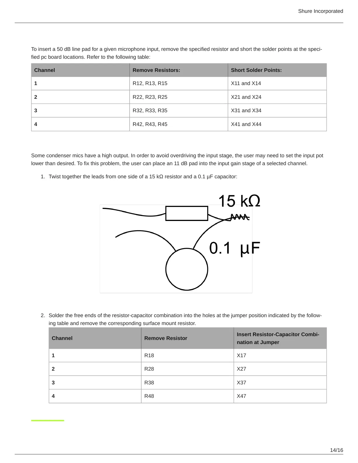
Twist together the leads from one side of a 15 kΩ resistor and a 0.1 µF capacitor:
Solder the free ends of the resistorcapacitor combination into the holes at the jumper position indicated by the follow
ing table and remove the corresponding surface mount resistor.
Channel Remove Resistor
Insert Resistor-Capacitor Combi-
nation at Jumper
1 R18 X17
2 R28 X27
3 R38 X37
4 R48 X47

 Loading...