Shure Incorporated
6/16
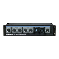
⑥ Auxiliary Input Channel (AUX IN).
A dedicated auxiliary-level input for the auxiliary channel.
⑦ Phantom Power Switch (12V PHANTOM).
Recessed switch turns on phantom power for microphone inputs 1-4.
⑧ Microphone Level Inputs (MIC LEVEL INPUTS).
Transformer-balanced, microphone-level XLR inputs.
Gain Control
Input Gain
The gain control knobs 14, located on the front panel, adjust the gain for both microphone and auxiliarylevel inputs of chan
nels 1-4 (see Figure1). For example, the channel 1 gain control is used for both the channel 1 microphone input (MIC LEVEL
INPUT 1) and the channel 1 auxiliary level input (AUX LEVEL INPUT 1). The auxiliary gain control knob (AUX IN) affects only
the auxiliary input (AUX IN).
Output Gain
The master output gain control knob (MASTER) adjusts gain to both the XLR balanced output (MIC/LINE LEVEL) and the aux
iliary level output (AUX LEVEL).
Figure 1
Output Level Meter
The six LEDs on the front panel labeled OUTPUT LEVEL METER illuminate to reflect the peak level of the mixed output signal
from the SCM268 (in reference to balanced line output) in dBu (0 dBu = 0.775 V).
Use the master gain control (MASTER) to adjust peak levels, as indicated by the LEDs. The red LED illuminates when the out
put is 2 dB below clipping.