5.2 Note on the swivel connector
NOTICE
Dama
ge to the connector unit from over-tightening!
The connector unit on the device has two opposite end positions.
■
Do not rotate the connector unit from either of the two end positions by more than
180°.
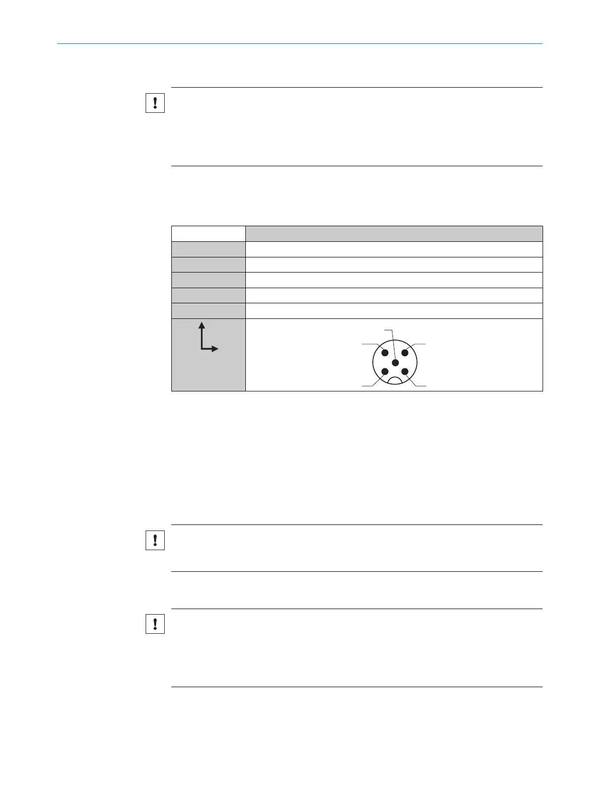
5.3 Pin assignment of the connections
5.3.1 Pin assignment of the connections
AS30
1 - BN L+
2 - WH Qa
3 - BU M
4 - BK C/Q
5 - GY MF
Legend
L+ = Suppl
y v
oltage
Qa = Analog output (edge information)
M = Ground
C/Q = Communication and switching output
MF = External input, external teach-in, Ql1 output, Ql2 output, input for changing the
reading and searching direction
NOTICE
Cros
stalk can occur on the analog output in IO-Link operation. Simultaneous operation
is not recommended.
5.4 Connecting the supply voltage
NOTICE
Risk of dama
ge to the device!
The device can become damaged if it is connected to a voltage supply that is already
switched on.
•
Only connect the device when the supply cable is de-energized.
The device must be connected to a power supply unit with the following properties:
•
Suppl
y v
oltage DC 18 V –30 V (SELV/PELV as per currently valid standards)
•
Electricity source with at least 3.1 W power
ELECTRICAL INSTALLATION 5
8022080.15LJ/2020-05-07 | SICK O P E R A T I N G I N S T R U C T I O N S | AS30 Core
15
Subject to change without notice