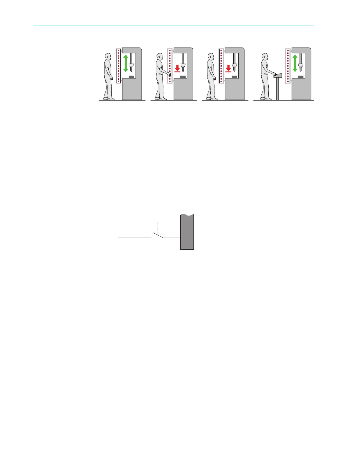
Figure 20: Schematic representation of operation with restart interlock
T
he dangerous state of the machine (!) is brought to an end if the light path is inter‐
rupted (") and is not re-enabled (§) until the operator presses the reset pushbutton
located outside the hazardous area ($). The machine can then be restarted.
Depending on applicable national regulations, a restart interlock must be available if it
is possible to stand behind the protective device. Observe IEC 60204-1.
4.4.1.1 Integrated restart interlock and reset
Prerequisites
•
A r
eset device, such as a reset pushbutton, is connected.
Figure 21: Electrical diagram of the reset device
Using an integrated restart interlock
T
he restart interlock is configured once the reset pushbutton has been connected.
The following applies to the restart interlock:
•
If the protective field is clear once the machine has been switched on or following
an interruption, the OSSDs do not switch to the ON state
•
If someone presses the reset pushbutton and then lets go of it when the protec‐
tive field is clear, the OSSDs switch to the ON state
•
The machine may not restart yet. The operator must also press the machine start
button after having pressed the reset pushbutton.
Single system
Onl
y one reset pushbutton may be connected to a single safety light curtain.
Connection options of the reset pushbutton in the single system:
•
M12, 8-pin system connection
•
Extension connection on the receiver
Further topics
•
"C
onfiguring the restart interlock", page 56
PROJECT PLANNING 4
8027140/2021-11-04 | SICK O P E R A T I N G I N S T R U C T I O N S | deTec4
33
Subject to change without notice
 Loading...


