Protective field height in mm Typical power consumption for
sender in W
Typical power consumption for
sender in W
1)
Resolution 30 mm Resolution 30 mm
2100 2.12 4.02
1)
Power discharged again via the OSSDs depending on the connected OSSD load must be added to the
t
able values.
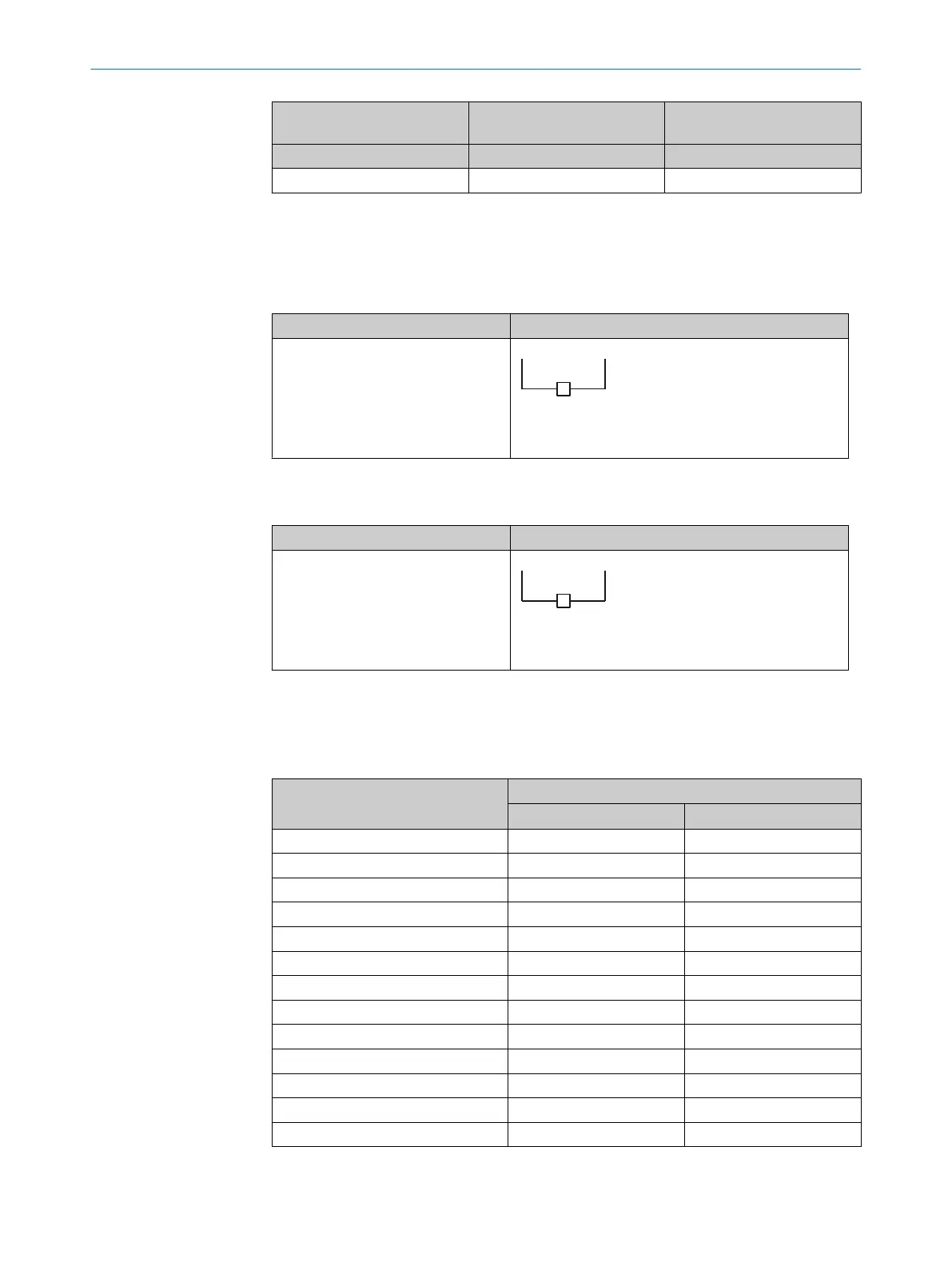
13.4 Length of cable
Table 34: Maximum lengths of cable for wire cross-section 0.34 mm
2
, c
opper wire
Single system
Separate connecting cables for
sender and r
eceiver
b ≤ 50 m c ≤ 15 m
S Control cabinet with safety relay or safety controller
Table 35: Maximum lengths of cable for wire cross-section 0.25 mm
2
, c
opper wire
Single system
Separate connecting cables for
sender and r
eceiver
b ≤ 35 m c ≤ 12 m
S Control cabinet with safety relay or safety controller
13.5 Table of weights
Table 36: Weight of sender and receiver
Protective field height in mm Weight in g
1)
s S
ender r Receiver
300 230 240
450 370 380
600 510 520
750 640 650
900 780 790
1050 910 920
1200 1050 1060
1350 1180 1190
1500 1320 1330
1650 1450 1460
1800 1590 1600
1950 1730 1740
2100 1860 1870
1)
Tolerance: ± 50 g.
TECHNICAL DATA 13
8027140/2021-11-04 | SICK O P E R A T I N G I N S T R U C T I O N S | deTec4
83
Subject to change without notice
 Loading...


