If the configuration was changed, the diagnostic LEDs flash white for 3 s upon activa‐
t
ion.
Once the safety light curtain is aligned and the protective field is clear (field indicator:
flashing yellow or lit up green), the alignment quality display switches off after a certain
period of time.
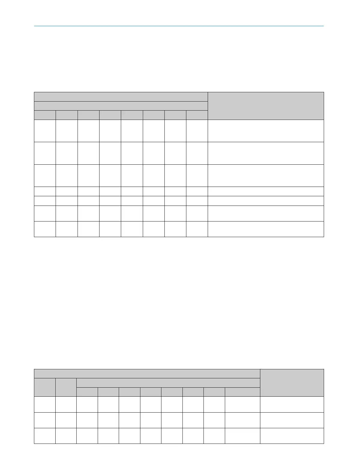
Table 23: Indication of the alignment quality
LEDs Meaning
Diagnostics LEDs
1 2 3 4 5 6 7 8
o o o o o o o o
Alignment is inadequate, or the protective field is
a
t least partially interrupted. The receiver cannot
synchronize with the sender.
O Blue o o o
At least one beam is synchronized.
However, the alignment is inadequate, or the pro‐
tective field is at least partially interrupted.
O Blue O Blue o o
The alignment or the signal strength is still not
suf
ficient for stable availability, or the protective
field is at least partially interrupted.
1)
O Blue O Blue O Blue o
Alignment is good, stable availability.
1)
2)
O Blue O Blue O Blue O Blue
Alignment is very good.
1)
O Blue O Blue
The topmost light beam (far from system plug) is
s
ynchronized.
O Blue O Blue
The bottommost light beam (near system plug) is
s
ynchronized.
o LED of
f. Ö LED flashes. O LED illuminates.
1)
If external device monitoring is configured and there is an EDM warning, diagnostic LED 1 flashes, while the other diagnostic LEDs 2, 3 and
4 indicate the alignment quality. If there is an error on the reset pushbutton, diagnostic LED 4 flashes, while the other diagnostic LEDs 1, 2
and 3 indicate the alignment quality.
2)
If the protective fields are very wide, there is a possibility that diagnostic LED 4 does not light up, even with optimal alignment.
11.3.2 Status indication
Overview
Dur
ing operation, the status of the safety light curtain is indicated with LEDs.
Sender
P
osition of the LEDs: see "Sender displays", page 16.
Receiver
P
osition of the LEDs: see "Receiver displays", page 17.
Table 24: LEDs on the receiver during normal operation
LEDs Meaning
OSSD Field Diagnostics LEDs
1 2 3 4 5 6 7 8
O
W
hite
EDM is configured.
O
White
Beam coding 1 or 2 is
conf
igured.
O
W
hite
Restart interlock is config‐
ur
ed.
11 TROUBLESHOOTING
72
O P E R A T I N G I N S T R U C T I O N S | deTec4 8027140/2021-11-04 | SICK
Subject to change without notice
 Loading...


