3
Quick-Start
CLV 210...CLV 212 Bar Code Scanner
© SICK AG · Division Auto Ident · Germany · All rights reserved
8 007 825/01-2002
Fig. 4. Pin assignment of the CLV 210...CLV 212: 15-pin D Sub HD connector/open cable end
5
1
96
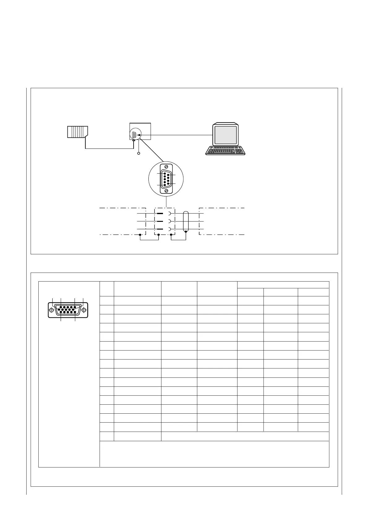
AMV/AMS 40 PC/Terminal
Connection via connection module
24 V DC (AMV)
230 V AC (AMS)
"AUX"
connector
Fig. 3. Block diagram: connecting the CLV 210...CLV 212
RxD
TxD
GND
TxD
RxD
GND
2
3
5
PC/
terminal
AMV/
AMS 40
RS 232
e.g. cable
no. 2 014 054
Table 1
Pin Color Function Terminal Host interface
1)
interfaces interface RS 232 RS 422/485 CL20 mA
1 red 24 V DC (in) - - - -
2 purple - RxD - - -
3 yellow - TxD - - -
4 red-black - - - Term
2)
-
5 black GND GND GND GND GND
6 light blue - - - RD+ R+
7 blue - - - RD- R-
8 light grey (turquoise) ---TD+T+
9 green - - - TD- T-
10 grey - - RxD - -
11 pink - - TxD - -
12 brown Dev Rdy
3)
----
13 orange Result
3)
----
14 white Sensor
4)
----
15 white-black SensGND
5)
----
white-green Screen
1) The CLV always transmits on the RS 232 and CL 20 mA (option: RS 422/485) interface.
One of the two interfaces must be activated via the Parametrization menu to
receive
data
(default: CL 20 mA interface)
2) Interface termination 3) Switching output 4) Switching input 5) see
Fig. 5
CLV 210...212