Quick-Start
CLV 210...CLV 212 Bar Code Scanners
4
© SICK AG · Division Auto Ident · Germany · All rights reserved
8 007 825/01-2002
Connecting the function interfaces
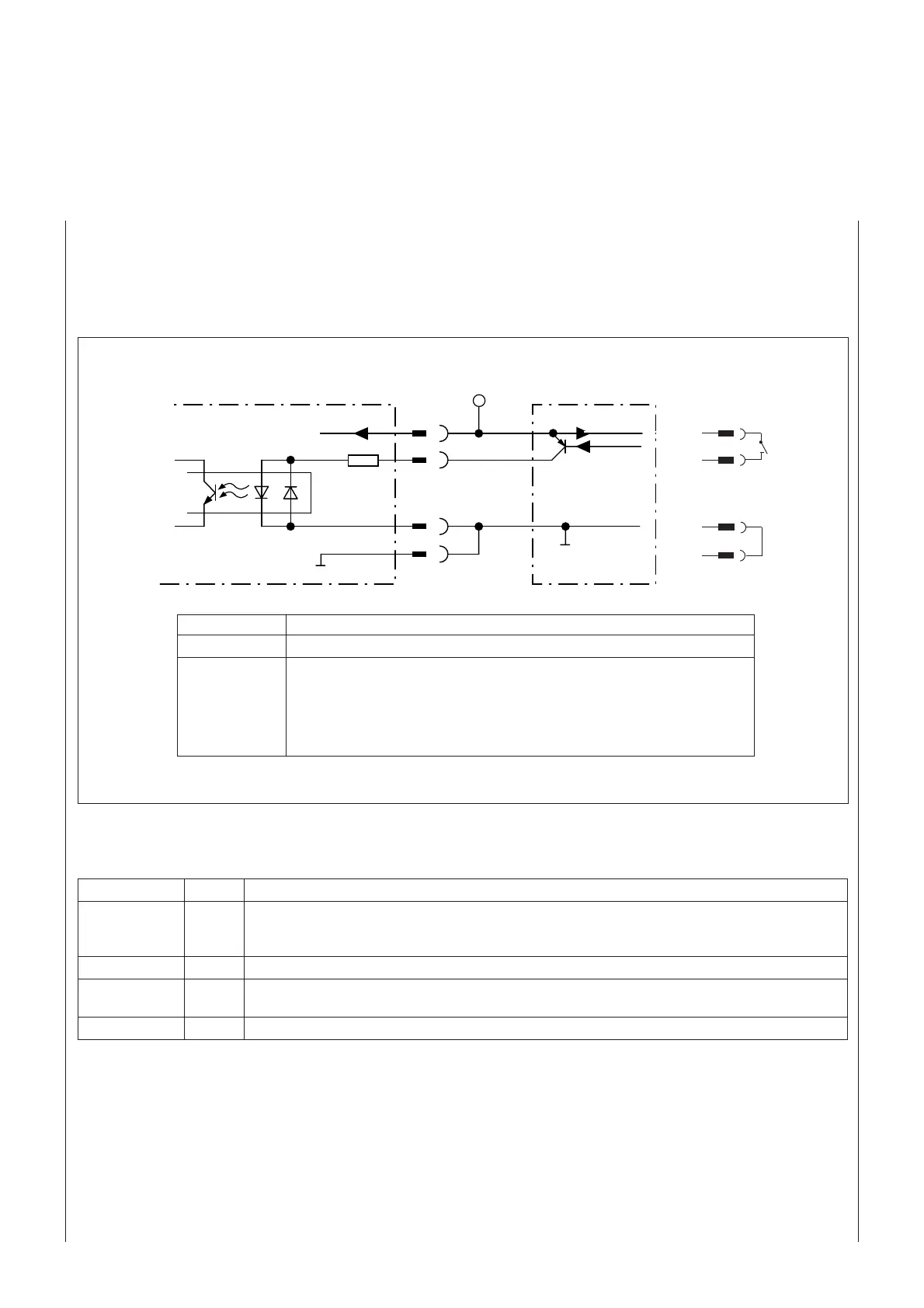
The CLV requires a suitable trigger (switch, sensor), as shown in
Fig. 5
, to trigger a reading process (clocking) in
Reading mode.
In the statistical
Percentage Evaluation
mode, the device operates independently of this trigger
thus enabling the read function to be tested directly. The connections of the two switching outputs "Device
Ready" and "Result" and the host interface are described in the
CLV 210...CLV 212 Operating Instructions
.
Fig. 5. "Sensor" reading-pulse input circuit for reading mode
LED Color Function
Device Ready green Indicates that the device is ready (reading mode).
This LED extinguishes as soon as the device switches to a different mode. It has the same indicator
function as the "Device Ready" switching output
Sensor green Indicates that the laser diode is activated during the reading process
Read Result green Corresponds to the "Result" switching output and its designed pulse function
(default: Good read, pulse duration 100 ms, non-inverted)
Data yellow Blinks during data transmission to the host
Table 3
6. Function of the LEDs
Switch
DC 24V
6K8
1
14
15
5
Sensor
GND
GND
DC 24V
DC 24V
Sens GND
CLV 210...CLV 212
PNP sensor
Switching function Start reading process when the input is energized (basic setting)
Features Opto-decoupled, non-interchangeable
Electrical values Low: -5V ≤ Vin ≤ +5 V
-0.5 mA ≤ Iin ≤ +0.5 mA
High: -30 V ≤ Vin ≤ -15 V
-2 mA ≤ Iin ≤ -5 mA
+15 V ≤ Vin ≤ +30 V
+2 mA ≤ Iin ≤ +5 mA
Table 2
24 V DC
24 V DC
24 V DC
1
14
15
5