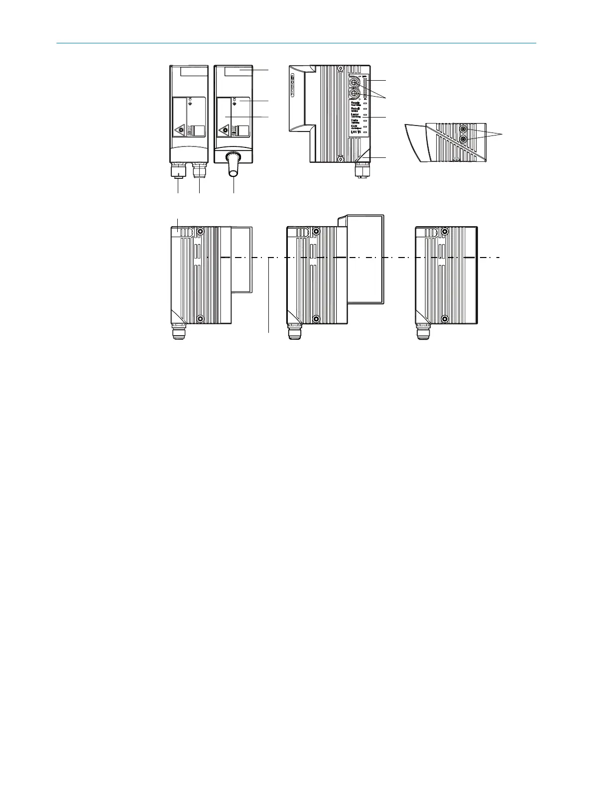
Figure 5: Device view of the CLV63x, CLV64x and CLV65x
1
Blind hole thread M5 (5 mm deep) for mounting (4x)
2
Laser warning label
3
Cover for micro SD card slot
4
Type label
5
Buttons for function selection/activation
6
Bar graph display
7
LEDs for indicating the status
8
Swivel connector
9
Central position of the deflected laser beam in the V-shaped aperture angle
ß
Male connector, M12, 12-pin or 17-pin, A-coded
à
Female connector, M12, 4-pin, D-coded (Ethernet)
á
Cable with male connector, D-Sub-HD, 15-pin
3 PRODUCT DESCRIPTION
16
O P E R A T I N G I N S T R U C T I O N S | CLV63x, CLV64x, CLV65x 8019588/129Z/2019-02-07 | SICK
Subject to change without notice
 Loading...


