Pin Signal Function
17 – –
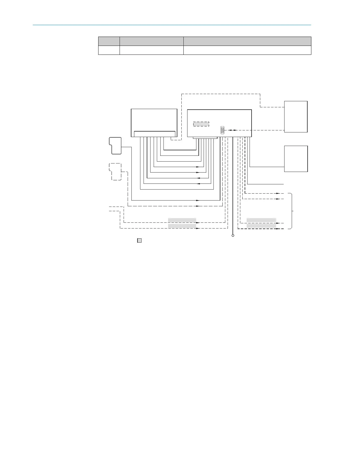
6.5 Connection diagrams
Standard version, cable, 15-pin male connector
“V
S
”
“Host”
“Aux 1”
“Result 2”
“Result 1”
“CAN”
“Sensor 2”
“Sensor 1”
“AUX”
CAN bus
“Result 1”
“Result 2”
PLC
CDB620/ CDM420 !
Connection module 4
“Host”
“Aux 1”
RS-232
HOST/PLC
Further data
processing 6
PC
Configuration
Diagnostics 5
Interfaces 2
RS-232/422
“Sensor 2”
“Sensor 1”
“External input 2”
“External input 1”
CMC600
â
á
à
V
S
8
= ß
“External output 2”
“External output 1”
Device 1
9 7
USB
“Aux 2”
“USB” (Aux 2) 3
Figure 34: Standard version: Electrical connections on the bar code scanner with connecting
cable, 15-pin male connector, D-Sub-HD
!
Here CDM420-0001 or CDM420-0006
1
Device
2
Interfaces
3
USB not required for CLV62x
4
Connection module
5
Configuration or diagnostics
6
Further data processing
7
External switching outputs
8
Supply voltage V
S
9
External switching inputs
ß
CMC600 parameter memory module is required to be able to use the additional external
switching inputs and outputs of the device (highlighted in gray)
à
Other functions
á
Application-dependent alternative stop reading cycle (e.g., photoelectric sensor) or travel
increment (incremental encoder)
â
Start/Stop reading sensor (e.g., photoelectric sensor)
6 ELECTRICAL INSTALLATION
46
O P E R A T I N G I N S T R U C T I O N S | CLV63x, CLV64x, CLV65x 8019588/129Z/2019-02-07 | SICK
Subject to change without notice
 Loading...


