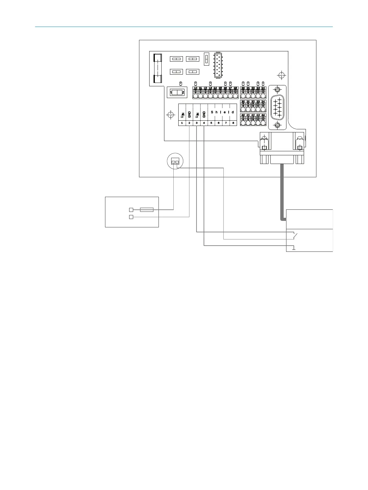
Figure 38: Supply voltage wiring for device and heating in CDB620-001 connection module
1
Supply voltage
2
GND
3
CLV switch (brown)
4
15-pin cable
5
Supply voltage (red)
6
GND (black)
7
F (fuse)
!
Control cabinet
§
CLV
$
Heating
%
Additional terminal (part number 6041383)
6.6 Wiring interfaces
6.6.1 Connecting the supply voltage
Connecting supply voltage to devices without heating
The device must be connected to a power supply unit with the following properties:
•
Supply voltage DC 24 V ± 20% (stabilized safety extra low voltage SELV as per cur‐
rently valid standards)
•
Electricity source with at least 30 W power
•
Additional 0.5 W output power when using the optional CMC600 parameter mem‐
ory module in the corresponding connection modules
ELECTRICAL INSTALLATION 6
8019588/129Z/2019-02-07 | SICK O P E R A T I N G I N S T R U C T I O N S | CLV63x, CLV64x, CLV65x
51
Subject to change without notice
 Loading...


