EasyManua.ls Logo

SICK CLV61 Series - User Manual

SICK CLV61 Series
114 pages
To Next Page IconTo Next Page
Loading...
O P E R A T I N G I N S T R U C T I O N S
CLV61x
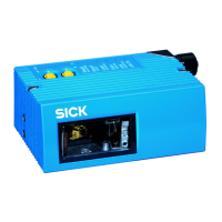
Fixed mount bar code scanner

Table of Contents

Other manuals for SICK CLV61 Series

Questions and Answers:

SICK CLV61 Series Specifications

General IconGeneral
BrandSICK
ModelCLV61 Series
CategoryBarcode Reader
LanguageEnglish

Summary

About this document

1.1 Information on the operating instructions

Explains the purpose, prerequisites, and intended audience for the operating instructions.

1.2 Scope

Defines the applicability and limitations of these operating instructions for the CLV61x device.

1.3 Explanation of symbols

Describes the meaning of various warning symbols and signal words used throughout the document.

1.4 Further information

Provides links and references to additional documentation and online resources for the device.

Safety information

2.1 Intended use

Details the proper application and purpose of the CLV61x fixed mount bar code scanner in industrial environments.

2.2 Improper use

Lists explicit uses considered improper, including hazardous areas, extreme conditions, and unauthorized modifications.

2.3 Cybersecurity

Highlights the need for a comprehensive cybersecurity concept for device operation and provides a link for information.

2.4 Limitation of liability

Outlines manufacturer's liability limitations concerning non-adherence to documentation or incorrect use.

2.5 Modifications and conversions

Warns that unauthorized modifications can lead to unforeseeable dangers and void warranty claims.

2.6 Requirements for skilled persons and operating personnel

Specifies the qualifications and training required for personnel handling the device safely.

2.7 Operational safety and particular hazards

Covers general operational safety, laser radiation hazards, and electrical safety precautions.

2.8 Switching off the device

Describes potential data loss when the device is switched off, focusing on temporary parameters.

2.9 Protection of the environment

Notes the device's construction with minimal environmental impact, avoiding silicon materials.

Product description

3.1 Product ID

Explains how to identify the device using its type label and other markings.

3.1.1 Type label

Details the information found on the device's type label, including conformity marks and test marks.

3.1.2 Type code

Describes the structure and meaning of the CLV61x product family's type code.

3.1.3 Scope of delivery

Lists the components that are included with the device upon delivery.

3.2 Product characteristics

Provides an overview of the device's physical characteristics and dimensions.

3.2.1 Device view

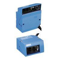
Illustrates the structure and dimensions of the CLV61x device with front and side viewing windows.

3.2.2 Device variants

Details the different interface applications and their features across CLV61x variants.

3.2.3 Product features and functions (overview)

Summarizes the key features and functions of the CLV61x device for easy understanding.

3.2.4 Operating principle

Explains the fundamental working principle of the device, including its components and interfaces.

Transport and storage

4.1 Transport

Provides safety guidelines and recommendations for the proper and safe transport of the device.

4.2 Unpacking

Offers instructions on how to unpack the device carefully to prevent damage.

4.3 Transport inspection

Guides users on how to inspect the delivery for completeness and potential transit damage.

4.4 Storage

Details the recommended conditions for storing the device to maintain its integrity.

MOUNTING

5.1 Overview of mounting procedure

Outlines the general steps involved in mounting the CLV61x device.

5.2 Preparing for mounting

Covers essential requirements and considerations before proceeding with device mounting.

5.2.1 Mounting requirements

Specifies space, environmental, and enclosure rating requirements for successful mounting.

5.2.2 Mounting device

Describes how to attach the device to mounting brackets, including SICK and user-supplied options.

5.3 Mounting location

Discusses key aspects for selecting the optimal installation location, including alignment and reflections.

5.4 Mounting device

Provides detailed, step-by-step instructions for mounting the device securely.

5.5 Mounting external components

Guides on mounting external modules like connection modules and read cycle sensors.

ELECTRICAL INSTALLATION

6.1 Safety

Emphasizes critical safety precautions and notes for electrical installation to prevent damage and injury.

6.1.1 Notes on the electrical installation

Provides specific warnings and recommendations for electrical connections and supply voltage.

6.1.2 Prerequisites for safe operation of the device

Details conditions for safe electrical operation, including grounding and equipotential bonding.

6.2 Wiring instructions

Offers general guidelines and best practices for wiring the device's electrical connections.

6.3 Pin assignments for electrical connections

Provides detailed pin assignments for the D-Sub HD, 15-pin male connector.

6.4 Connection diagrams

Presents visual diagrams illustrating device and module connection configurations.

6.5 Wiring interfaces

Covers the procedures for wiring various interfaces, including supply voltage and data connections.

COMMISSIONING

7.1 Overview of the commissioning steps

Outlines the sequence of tasks required for commissioning the device.

7.2 SOPAS ET configuration software

Introduces the SOPAS ET software and its role in device configuration and diagnostics.

7.3 Initial commissioning

Describes the process of initial setup, parameterization, and saving configurations.

7.4 Adjusting the device for operational use

Details the steps for final adjustments and alignment for optimal reading performance.

7.5 Fine adjustment and further configuration

Explains advanced configuration options like Quickstart, application wizards, and code settings.

OPERATION

8.1 Operating and status indicators

Explains how to interpret the device's LED indicators for status and operational feedback.

8.1.1 Optical display

Details the visual display behavior of the device's sensor LED, including color and state.

8.1.2 Acoustic signaler (beeper)

Describes the device's audible signals (beeper) and how they indicate different operating modes and results.

8.2 Operating options

Outlines how the device can be configured locally or via command strings for application use.

MAINTENANCE

9.1 Maintenance plan

Lists preventive maintenance tasks, their intervals, and required personnel.

9.2 Cleaning

Provides instructions for cleaning the device's viewing window and housing to maintain performance.

TROUBLESHOOTING

10.1 Overview of possible errors and faults

Summarizes common errors and faults, categorizing them by situation like mounting or configuration.

10.2 Detailed fault analysis

Guides on analyzing faults using device LEDs and system information, including status logs.

10.3 Repairs

Specifies that repairs must be performed by authorized personnel and outlines warranty implications.

10.4 Disassembly

Provides steps for safely dismantling the device for replacement or repair.

10.5 Returns

Details the procedure for returning devices for service, emphasizing consultation with SICK Service.

10.6 Device exchange with transmission of the current configuration data

Explains how to replace a device and transfer its configuration data using backup methods.

DECOMMISSIONING

11.1 Disposal

Provides guidelines for environmentally friendly disposal of the device according to regulations.

TECHNICAL DATA

12.1 Features

Lists the key technical features and specifications of the CLV61x product family.

12.2 Performance

Details performance metrics such as readable code structures, bar code types, and print ratio.

12.3 Interfaces

Describes the technical data for the various interfaces available on CLV61x devices.

12.4 MechanicsElectronics

Covers mechanical and electrical specifications including housing, dimensions, safety, and power consumption.

12.5 Ambient data

Specifies the environmental conditions the device can operate under, including EMC and temperature limits.

12.6 Dimensional drawings

Refers to external drawings that detail the device's physical dimensions.

12.7 Reading field diagrams (working ranges)

Provides graphical representations of the device's reading field performance under various conditions.

ACCESSORIES

13.1 Dimensional drawings of brackets

Shows dimension drawings and mounting information for SICK brackets.

13.1.1 Quick release in combination with mounting bracket

Illustrates the mounting of brackets involving quick release components.

ANNEX

14.1 Declarations of conformity and certificates

Provides information on device compliance and links to download certificates.

14.2 UL conformity

Details the UL certification status, requirements, and limitations for the device.

14.3 Dimensional drawings electronic formats

Offers links to download current dimensional drawings and CAD data in various electronic formats.

14.4 Signal assignment of cables with open cable end at one end

Specifies pin assignments, signal functions, and wire colors for various cables.

14.5 Connection diagrams of connection module CDB620-001

Presents connection diagrams for integrating the device with the CDB620-001 module.

14.6 Connection diagrams of connection module CDM420-0001

Presents connection diagrams for integrating the device with the CDM420-0001 module.

14.7 Connection diagrams of connection module CDM420-0006

Presents connection diagrams for integrating the device with the CDM420-0006 module.

14.8 Abbreviations used

Provides an alphabetical list of abbreviations and their full meanings used in the manual.

Related product manuals