■
Depending on the device, at least two M5 screws for mounting the device
– The screw length depends on the wall thickness of the mounting device.
– The maximum screw in-depth in the device is 5 mm from the housing sur‐
face.
5.3 Mounting location
Observe the following aspects when selecting the installation location:
•
Basic assignment of the scan line to the bar code
•
Reading distance to bar code and aperture angle α
•
Angular orientation of the device to the bar code
•
Avoidance of surface reflections
•
Counting direction of the reading angle (position of the bar code within the scan
line)
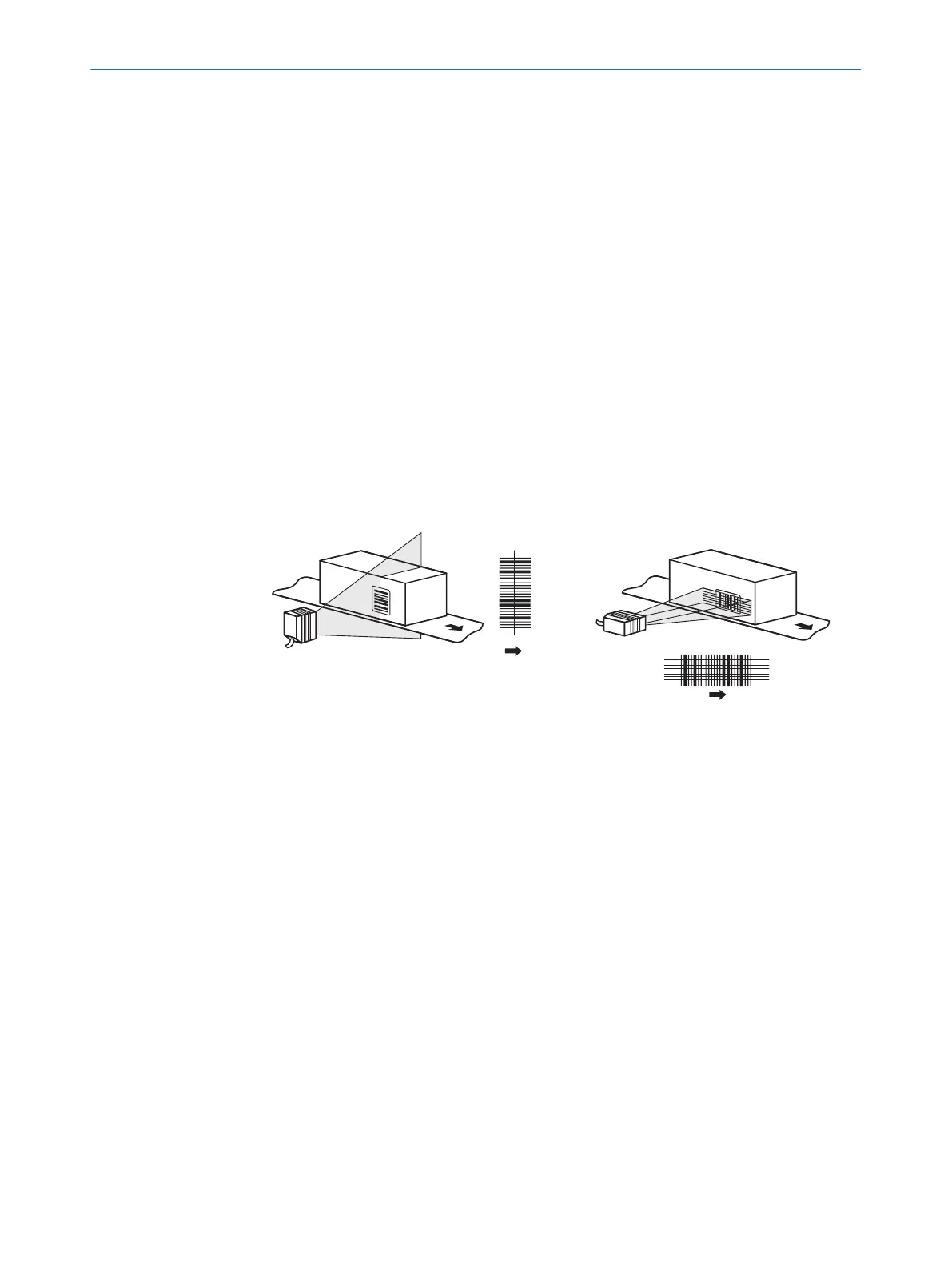
5.3.1 Basic assignment of the scan line to the bar code
The principle assignment of the scan line to the bar code on the object depends on the
sensor type of the device: Line scanner with line scanning or raster scanner with raster
scanning
line scanner raster scanner
1 2
Figure 10: Allocation of scan line(s) to bar code and conveyor direction
1
Line scanner
2
Grid scanner
5.3.2 Reading distance to the bar code and aperture angle α
The maximum distance from the viewing window of the device to the bar code may
not exceed the limit values for the device. Because of the V-shaped deflection of the
beams, the usable length of the scan line for evaluation (reading field height) depends
on the reading distance.
5 MOUNTING
28
O P E R A T I N G I N S T R U C T I O N S | CLV61x 8017840/19OF/2021-10-28 | SICK
Subject to change without notice
 Loading...


