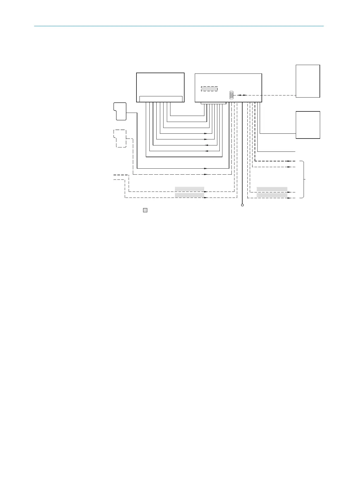
6.4 Connection diagrams
“V
S
”
“Host”
“Aux”
“Result 2”
“Result 1”
“CAN” 3
“Sensor 2”
“Sensor 1”
“AUX”
CAN bus 3
“Result 1”
“Result 2”
PLC
CDB620/ CDM420 !
Connection module 4
“Host”
“Aux 1”
RS-232
HOST/PLC
Further data
processing 6
Computer
Configuration
Diagnostics 5
Interfaces 2
RS-232
“Sensor 2”
“Sensor 1”
“External input 2”
“External input 1”
CMC600
â
á
à
V
S
8
= ß
“External output 2”
“External output 1”
Device 1
9 7
!
CDB620-001 or CDM420
1
Device
2
Interfaces
3
CAN
4
Connection modules
5
Configuration or diagnostics
6
Data further processing
7
External digital outputs
8
Supply voltage V
S
9
External digital inputs
ß
The CM600 parameter cloning module is required in the connection module in order to be
able to use the additional external digital inputs and outputs of the device (highlighted in
gray)
à
Other functions
á
Application-specific alternative stop reading pulse (e.g., photoelectric sensor) or travel
increment (incremental encoder)
â
Start/Stop reading pulse (e.g., photoelectric sensor)
6.5 Wiring interfaces
6.5.1 Connecting the supply voltage
Connect the device only to a power supply unit that has the following properties:
•
Stabilized safety extra-low voltage SELV according to currently valid standards
•
Supply voltage, depending on the length of the connecting cable:
°
10 V DC to 30 V DC, for devices with connecting cable 0.6 m up to max. 3 m
°
12 V DC up to 30 V DC, for devices with connecting cable 3 m up to max. 6 m
6 ELECTRICAL INSTALLATION
40
O P E R A T I N G I N S T R U C T I O N S | CLV61x 8017840/19OF/2021-10-28 | SICK
Subject to change without notice

 Loading...


