2
Illustration may differ
2
Illustration may differ
Table 22: Signal assignment of adapter cable with open end
Pin Signal at computer Function Wire color
1 – – –
2 RxD (RS-232), host Host interface (receiver) Brown
1)
3 TxD (RS-232), host Host interface (sender) Blue
2)
4 – – –
5 GND Ground Black
6 ... 9 – – –
1)
Connect to the “TxD Host” terminal in the CDB/CDM connection module
2)
Connect to the “RxD Host” terminal in the CDB/CDM connection module
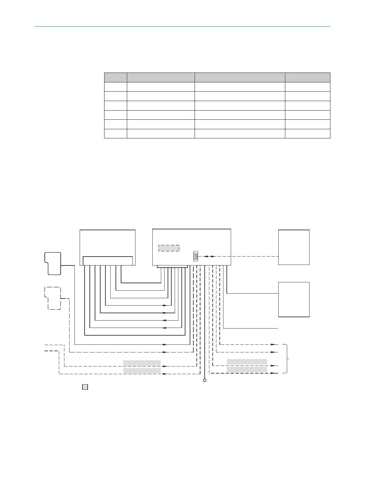
14.5 Connection diagrams of connection module CDB620-001
14.5.1 Connection of the device to CDB620-001
Device = CLV61x-xx0xxx (serial variant)
“V
S
”
“Sensor 2”
“Host”
“Aux”
“Result 2”
“Result 1”
“CAN”
“Sensor 2”
“Sensor 1”
“Sensor 1”
V
S
8
“AUX”
PLC
CAN bus
“Result 1”
“Result 2”
CDB620-001
Connection module 4
“Aux”
RS-232
HOST/PLC
Further data
processing 6
Computer
Configuration
Diagnostics 5
Device 2
Interfaces 3
“Host”
RS-232
1
á
à
= ß
CMC600
“External input 1”
“External input 2”
“External output 1”
“External output 2”
9 7
Figure 40: Connection of the device to peripherals via CDB620-001 (overview)
1
External trigger sensor, e.g., for read cycle generation
2
Device
3
Interfaces
4
Connection module
5
Configuration or diagnostics
6
Data further processing
14 ANNEX
76
O P E R A T I N G I N S T R U C T I O N S | CLV61x 8017840/19OF/2021-10-28 | SICK
Subject to change without notice

 Loading...


