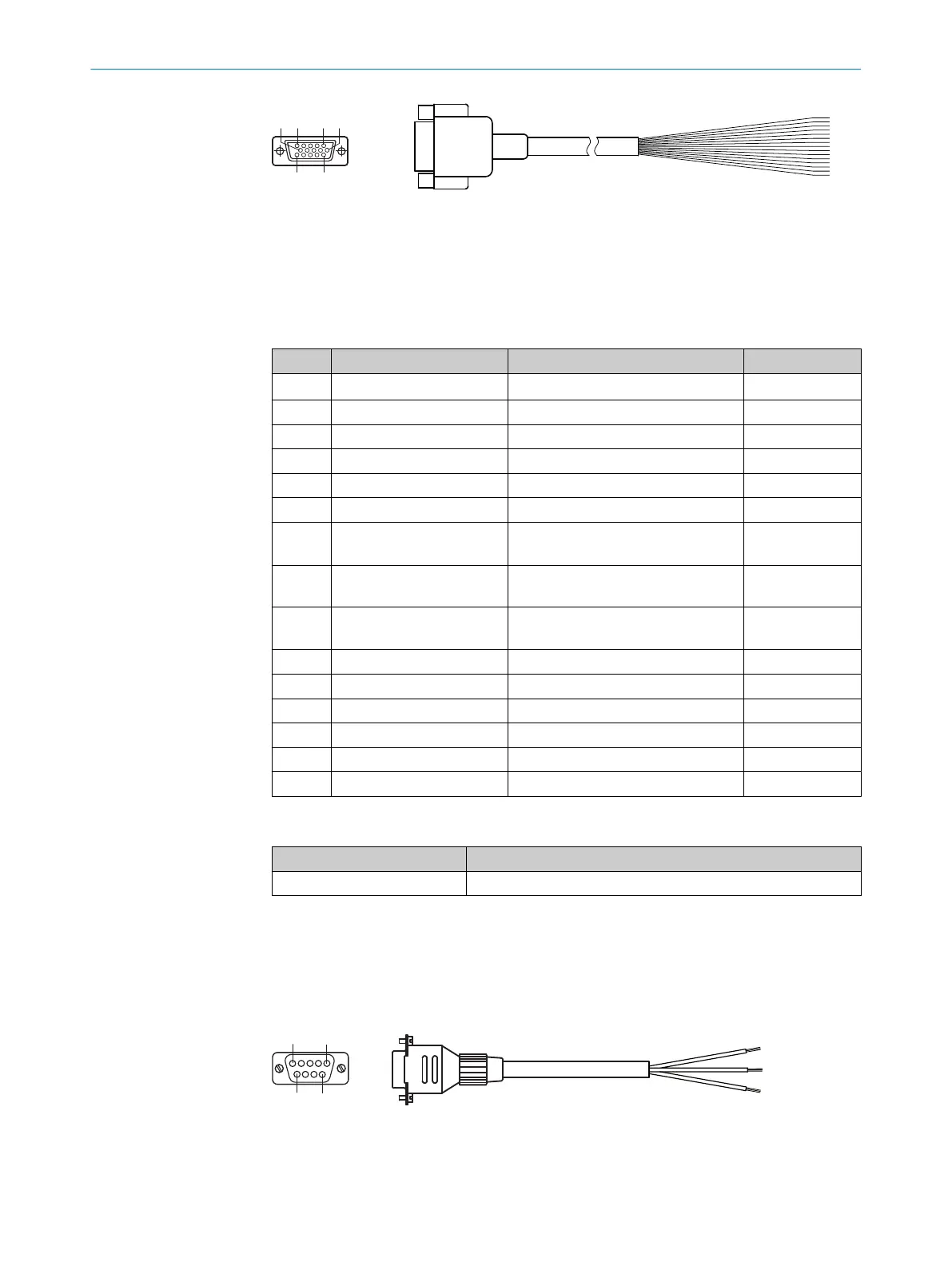
Figure 38: Adapter cable, part no. 2043413
1
Female connector, D-Sub-HD, 15-pin (view from front)
2
Illustration may differ
2
Illustration may differ
Table 21: Signal assignment of adapter cable with open end
Pin Signal Function Wire color
1 V
S
Supply voltage Red
2 RxD (RS-232), Aux AUX interface (receiver) Violet
3 TxD (RS-232), Aux AUX interface (sender) Yellow
4 Sensor 2 Digital input 2 Red-black
5 GND Ground Black
6 RD+ (RS-422/485), host Host interface (receiver+) Light blue
7 RD– (RS-422/485), host
RxD (RS-232), host
Host interface (receiver–) Blue
8 TD+ (RS-422/485), host Host interface (sender+) Light-gray or tur‐
quoise
9 TD– (RS-422/485), host
TxD (RS-232), host
Host interface (sender-) Green
10 CAN H CAN bus (IN/OUT) Gray
11 CAN L CAN bus (IN/OUT) Pink
12 Result 1 Digital output 1 Brown
13 Result 2 Digital output 2 Orange
14 Sensor 1 Digital input 1 White
15 SensGND Digital input ground White-black
14.4.2 Host interface RS-232 via connection module CDB/CDM to host (computer)
Device Connection module
CLV61x CDB620-001, CDM420-0001, -0004, -0006, -0007
Adapter cable, straight female connector, open end
Part no. 2020319 (3 m), unshielded
Ambient temperature range:
For fixed installation: –25 °C to +40 °C
Figure 39: Adapter cable, part no. 2020319
1
Female connector, D-Sub, 9-pin (front view)
ANNEX 14
8017840/19OF/2021-10-28 | SICK O P E R A T I N G I N S T R U C T I O N S | CLV61x
75
Subject to change without notice

 Loading...


