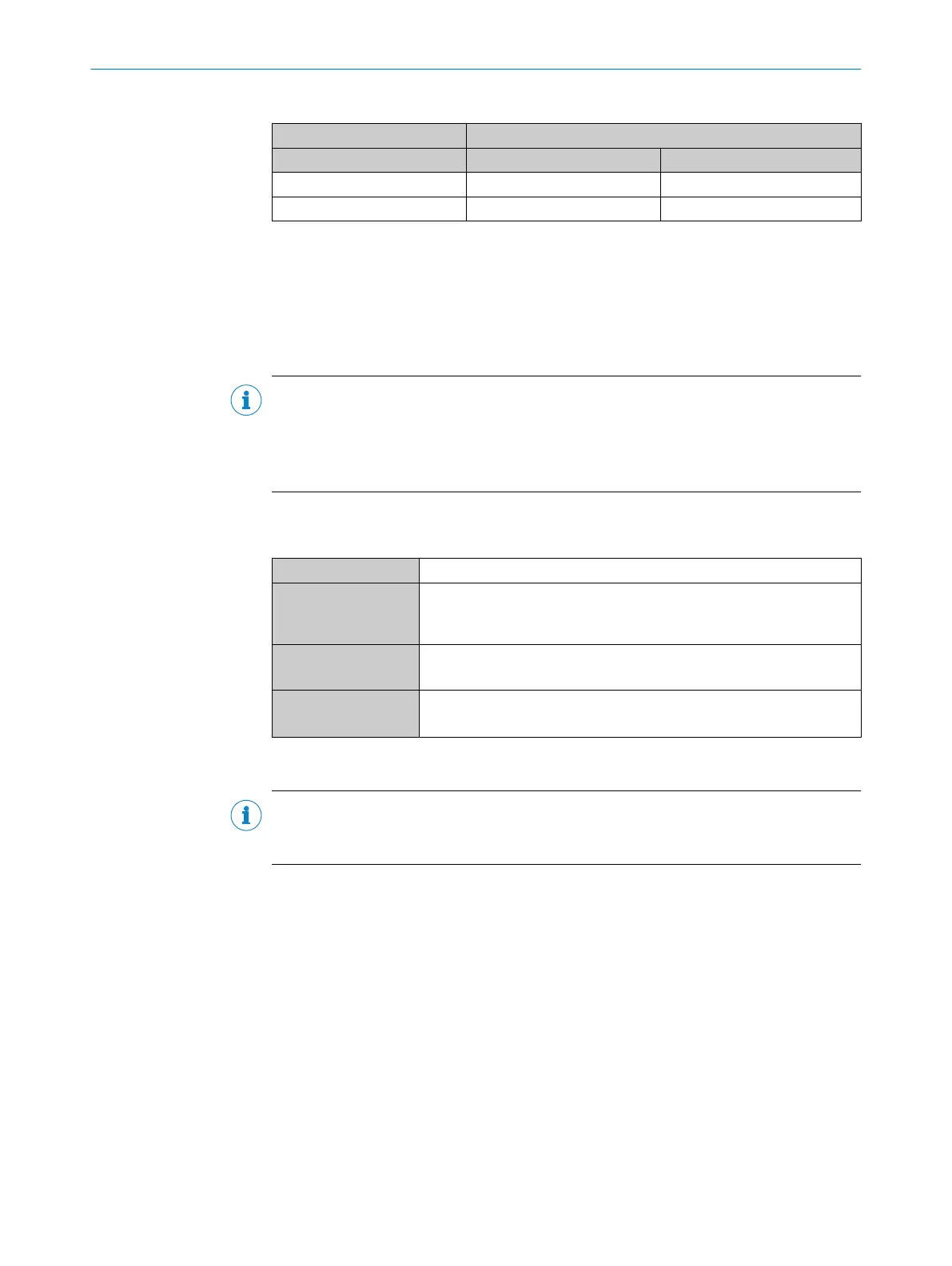
Table 43: Assignment of placeholders to the external digital outputs
Device CDM420-0001
External output A Signal B Terminal C
1 Aux Out 1 40
2 Aux Out 2 30
Functional principle of the external digital outputs
The optional CMC600 parameter cloning module in combination with the CDB or CDM
connection module offers two additional digital outputs for the device. The outputs are
available at the respective terminals of the connection module. To distinguish them
from the physical digital outputs directly on the device, these addition outputs via the
CMC600 are designated as “external outputs”.
NOTE
The device transmits the statuses of its logical outputs to the CMC600 via its serial
data interface. The CMC600 converts the statuses into switching signals on its physical
digital outputs.
The digital outputs are not suitable for time-critical applications.
Characteristic data of the digital outputs
Table 44: Characteristic data of the digital outputs “External output 1” and “External output 2”
Type Switching
Switching behavior PNP switching to supply voltage V
S
Default settings in the device: no function, logic: not inverted (active
high)
Properties
•
Short-circuit protected and temperature protected
•
Not electrically isolated from the supply voltage V
S
Electrical values 0 V ≤ V
out
1)
≤ V
S
(V
S
− 1.5 V) ≤ V
out
≤ V
S
at I
out
2)
≤ 100 mA
1)
Output voltage
2)
Output current
NOTE
Assign the functions for the digital outputs in the device using a configuration tool, e.g.,
the configuration software SOPAS ET.
14.7 Connection diagrams of connection module CDM420-0006
14.7.1 Connection of the device to CDM420-0006
Device = CLV61x-xx0xxx (serial variant)
ANNEX 14
8017840/19OF/2021-10-28 | SICK O P E R A T I N G I N S T R U C T I O N S | CLV61x
99
Subject to change without notice

 Loading...


