“V
S
”
“Sensor 2”
“Host”
“Aux”
“Result 2”
“Result 1”
“CAN”
“Sensor 2”
“Sensor 1”
“Sensor 1”
V
S
8
“AUX”
PLC
CAN bus
“Result 1”
“Result 2”
CDM420-0006
Connection module 4
“Aux”
RS-232
HOST/PLC
Further data
processing 6
Computer
Configuration
Diagnostics 5
Device 2
Interfaces 3
“Host”
RS-232
1
á
à
= ß
CMC600
“External input 1”
“External input 2”
“External output 1”
“External output 2”
9 7
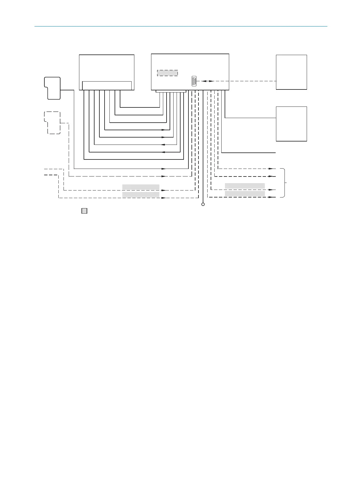
Figure 62: Connection of the device to peripherals via CDM420-0006 (overview)
1
External trigger sensor, e.g. for read cycle generation
2
Device
3
Interfaces
4
Connection module
5
Configuration or diagnostics
6
Data further processing
7
External digital outputs (switching)
8
Supply voltage V
S
9
External digital inputs (switching)
ß
The optional CMC600 parameter cloning module is required in the connection module in order to use the additional
external digital inputs and outputs of the device (highlighted in gray).
à
Other functions
á
Application-dependent alternative stop reading cycle (e.g. photoelectric sensor) or travel increment (incremental
encoder)
14.7.2 Wiring overview of the CDM420-0006
Device = CLV61x-xx0xxx (serial variant), 1 digital input used
14 ANNEX
100
O P E R A T I N G I N S T R U C T I O N S | CLV61x 8017840/19OF/2021-10-28 | SICK
Subject to change without notice

 Loading...


