6.3 Pin assignments for electrical connections
CLV61x CAN / FIELDBUS
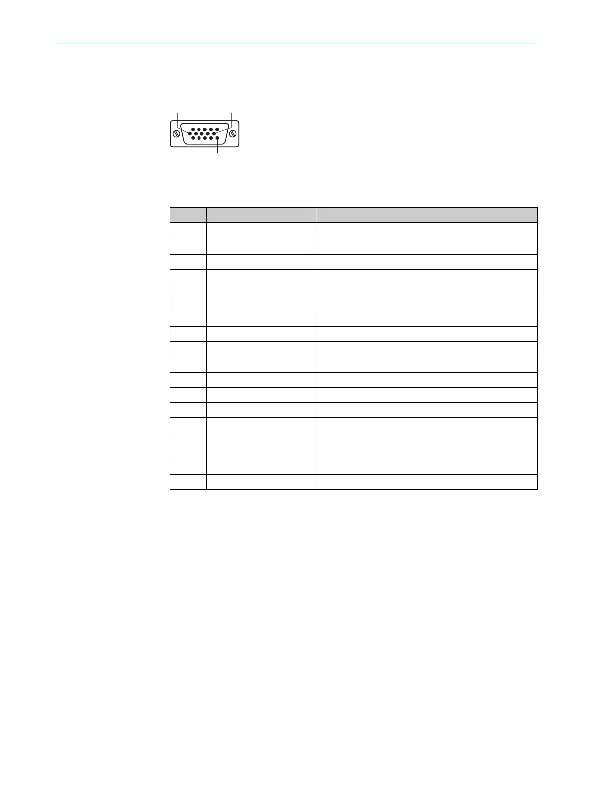
Figure 23: Male connector, D-Sub-HD, 15-pin
Table 8: Male connector pin assignment, D-Sub-HD, 15-pin
Pin Signal Function
1 V
S
1)
Supply voltage
2 RxD (RS-232), Aux AUX interface (receiver)
3 TxD (RS-232), Aux AUX interface (sender)
4 Sensor 2 Digital input (function adjustable, e.g., stop external
reading pulse)
5 GND Ground
6 n.c. Not connected
7 RxD (RS-232), Host Host interface (receiver)
8 n.c. Not connected
9 TxD (RS-232), Host Host interface (sender)
10 CAN_H CAN bus (IN/OUT)
11 CAN_L CAN bus (IN/OUT)
12 Result 1 Digital output, function adjustable
13 Result 2 Digital output, function adjustable
14 Sensor 1 Digital input (function adjustable, e.g. start external
reading pulse)
15 SensGND Common ground of the digital inputs
‒ ‒ Screen
1)
Level and type of supply voltage see "Mechanics/Electronics", page 63.
ELECTRICAL INSTALLATION 6
8017840/19OF/2021-10-28 | SICK O P E R A T I N G I N S T R U C T I O N S | CLV61x
39
Subject to change without notice

 Loading...


