line scanner raster scanner
reading distance reading distance
1 2
3
3
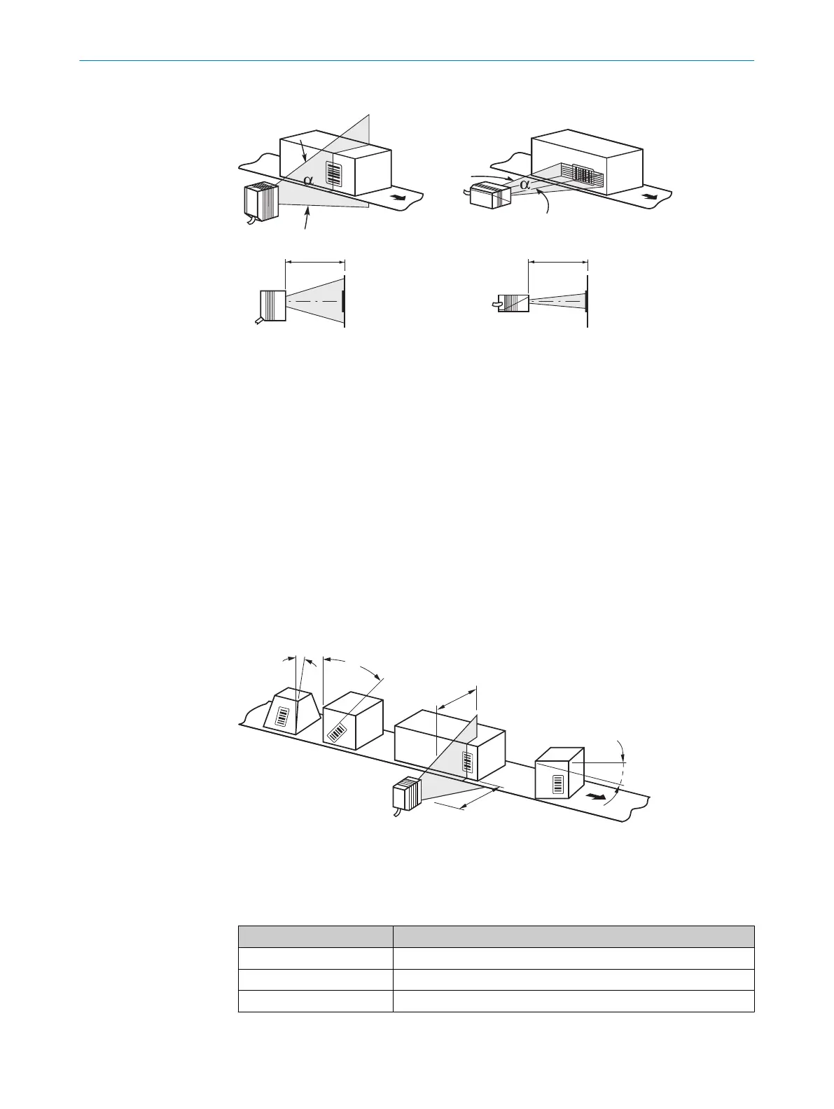
Figure 11: Definition of the reading distance and the aperture angle α
1
Line scanner
2
Grid scanner
3
Reading distance
In the specification diagrams (see "Reading field diagrams (working ranges)",
page 64), the height of the reading field is shown as a function of the reading distance
for different resolutions (module widths).
5.3.3 Angular orientation of the device
When the scan line sweeps across the bar code at nearly a right angle, the optimal
alignment of the device has been achieved (azimuth and tilt). Possible reading angles
that may occur between the scan line and the bar code must be taken into account.
This applies to all three levels in the room.
To avoid surface reflections, select a rotation angle of approx. 15° from the perpendicu‐
lar to the bar code, see "Avoiding surface reflections", page 30.
Figure 12: Line scanner: Occurring reading angle between scan line and bar code
1
Depth of field
2
Reading distance
Table 7: Permitted read angle between scan line and bar code
Angle Limit Value
Tilt α Max. 30°
Pitch β Max. 45°
Skew γ Max. 45°
MOUNTING 5
8017840/19OF/2021-10-28 | SICK O P E R A T I N G I N S T R U C T I O N S | CLV61x
29
Subject to change without notice

 Loading...


