NOTE
The specified maximum values can only be achieved if conditions are optimal. The
actual maximum depends on module width, code type, print contrast, ambient light,
distance and scanning frequency.
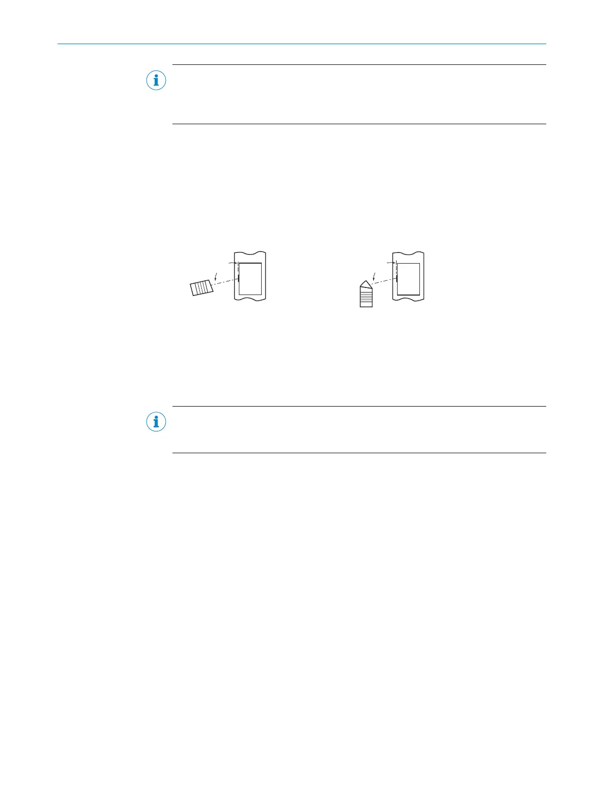
5.3.4 Avoiding surface reflections
If the light of the scan line(s) hits the surface of the bar code exactly perpendicular,
disturbing reflections may occur.
To avoid this effect when receiving the backscattered light, mount the device so that the
outgoing light is tilted relative to the perpendicular.
Line scanner
(viewing window on front)
Line scanner
(viewing window on side)
(Top view)(Top view)
105° 105°
1 2
3
3
Figure 13: Avoiding surface reflections on the example line scanner: Angle between light emitted
and bar code (tilting away from vertical)
1
Line scanner (front viewing window)
2
Line scanner (side viewing window)
3
Supervision
NOTE
When the scan line is tilted approx. 15° from the perpendicular, optimum results are
obtained.
5.3.5 Counting direction of the reading angle
The device can scan and decode several bar codes at each reading.
The device determines the location-specific read diagnostics data per bar code and
optionally outputs these data in the read result:
Reading angle (RA value)
■
This value specifies the angle at which the deflected scanning beam detects the
bar code center with the red scan line in the scan plane. This value is within the
aperture angle of the device.
By determining the respective RA value, identical bar codes (code type, code length,
and data content) can be separated, and the bar code data can be assigned based on
its position on the object.
5 MOUNTING
30
O P E R A T I N G I N S T R U C T I O N S | CLV61x 8017840/19OF/2021-10-28 | SICK
Subject to change without notice

 Loading...


