4
Grounding point 3
5
Insulated mounting
6
Grounding point 2
7
Ground potential difference
8
Grounding point 1
9
Metal housing
ß
Shielded electrical cable
Even in the event of large differences in the ground potential, ground loops are effec‐
tively prevented. As a result, equalizing currents can no longer flow via the cable shields
and metal housing.
NOTICE
The voltage supply for the device and the connected peripheral devices must also guar‐
antee the required level of insulation.
Under certain circumstances, a tangible potential can develop between the insulated
metal housings and the local ground potential.
6.3 Wiring notes
NOTICE
Faults due to incorrect wiring.
Incorrect wiring may result in operational faults.
■
For data transmission, use only screened cables with twisted-pair wires.
■
Follow the wiring notes precisely.
NOTE
Preassembled cables can be found online at:
•
www.sick.com/CLV63x
•
www.sick.com/CLV64x
•
www.sick.com/CLV65x
All electrical connections of the device are configured as M12 round connectors or as a
cable with D-Sub-HD male connector, depending on the type. The IP65/IP69K enclo‐
sure rating is only achieved with screwed plug connectors or protective caps.
All electrical connections of the device are configured as M12 round connectors or as a
cable with D-Sub-HD male connector, depending on the type. The IP65 enclosure rating
is only achieved with screwed plug connectors or protective caps.
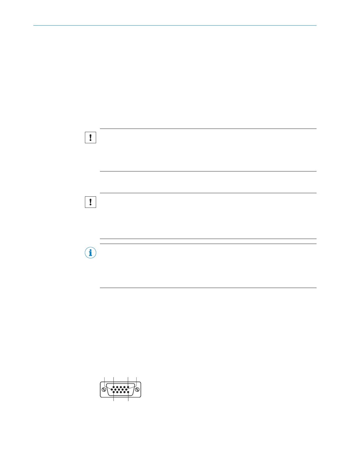
6.4 Pin allocation of the connections
Device connections with cable and male connector (standard version)
Figure 30: Male connector, D-Sub-HD, 15-pin
ELECTRICAL INSTALLATION 6
8019588/129Z/2019-02-07 | SICK O P E R A T I N G I N S T R U C T I O N S | CLV63x, CLV64x, CLV65x
43
Subject to change without notice
 Loading...


