NOTE
The device loses its UL certification if the connecting cables are extended over 2 m.
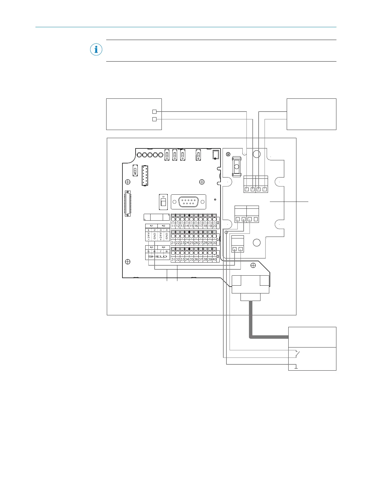
Using connection module CDM420-0001
The incoming/continuing supply cables in the CDM420-0001 are connected on termi‐
nal block U
IN
of the additional connection circuit board.
F1
24 V GND 24 V GND
PD1
24 V GND NCCLV
SWITCH
U
IN
24 V GND
CDM
HEATER
1
2
!
"
1 1
22
5
3 4
§
%
$
6
7
8
Figure 37: Supply voltage wiring for device and heating in CDM420-0001 connection module
1
Supply voltage
2
GND
3
GND (black)
4
Supply voltage (red)
5
15-pin cable
6
CLV switch (brown)
7
Supply voltage (red)
8
GND (black)
!
Control cabinet
ELECTRICAL INSTALLATION 6
8019588/129Z/2019-02-07 | SICK O P E R A T I N G I N S T R U C T I O N S | CLV63x, CLV64x, CLV65x
49
Subject to change without notice
 Loading...


