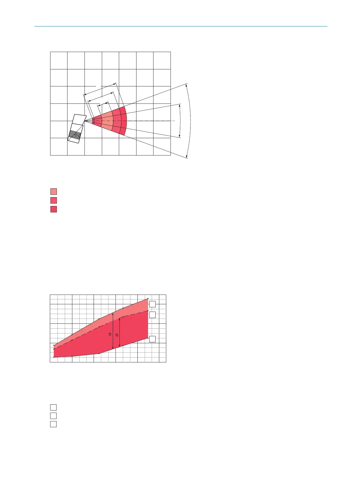
Deflection range in mm (inch) 1
Reading distance in mm (inch)
2
–100
(–3.94)
0
0
40°
20°
b
Resolution 3
a: 0.20 mm (7.9 mil)
c: 0.50 mm (19.7 mil)
b: 0.35 mm (13.8 mil)
a
c
400
(15.75)
–200
(–7.87)
200
(7.87)
400
(15.75)
500
(19.69)
–100
(–3.94)
300
(11.81)
100
(3.94)
300
(11.81)
–200
(–7.87)
100
(3.94)
200
(7.87)
Figure 58: Oscillating mirror deflection width diagram CLV632, short range, oscillating mirror
1
Deflection width in mm (inch)
2
Reading distance in mm (inch)
3
Solution
12.6.3 Overview of CLV64x reading field diagrams
12.6.3.1 standard resolution
Reading distance in mm (inch) 1
Focus position in mm (inch) 2
380
(14.96)
320
(12.6)
260
(10.24)
200
(7.87)
140
(5.51)
80
(3.15)
600
(23.62)
400
(15.75)
200
(7.87)
0
Resolution 0.5 mm (19.7 mil)
4
Max. reading distance (aperture angle 25°) 5
Max. reading distance (aperture angle 50°) 6
Min. reading distance 7
A
B
C
A
B
C
DOF = 25°
DOF = 50°
For devices with plastic reading window, the depth of
field is reduced by approx. 10 %. 3
Figure 59: Reading field diagram CLV640, standard density, resolution 0.5 mm (dynamic), reading window on front
1
Reading distance in mm (inch)
12 TECHNICAL DATA
84
O P E R A T I N G I N S T R U C T I O N S | CLV63x, CLV64x, CLV65x 8019588/129Z/2019-02-07 | SICK
Subject to change without notice
 Loading...


