Table 5: Pin assignment of the “ETHERNET 1 ...3” connections (GBit)
Pin Signal Function
1 TRD0_P Sender+/receiver+0
2 TRD0_N Sender–/receiver– 0
3 TRD1_P Sender+/receiver+1
4 TRD1_N Sender–/receiver– 1
5 TRD3_P Sender+/receiver+3
6 TRD3_N Sender–/receiver– 3
7 TRD2_N Sender–/receiver– 2
8 TRD2_P Sender+/receiver+2
“FAN” connection (depends on variant)
Figure 10: Female connector, M12, 5-pin, A-coded
NOTE
Device with variant A connection mask: available.
Device with variant B connection mask: not available. The device has an integrated fan
connection.
NOTE
The “FAN” connection is used exclusively for supplying voltage to and controlling the
device’s fan.
Table 6: Pin assignment of the “FAN” connection
Pin Signal Function
1 V
S OUT
FAN Fan supply voltage (12 V)
2 Tacho FAN Fan RPM signal
3 GND FAN Fan ground
4 N. c. –
5 N. c. –
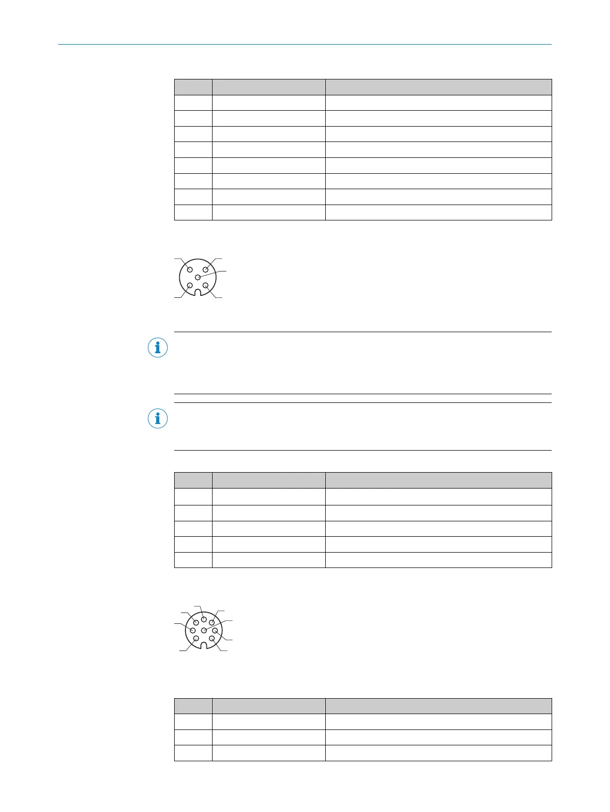
"LIGHT 1” connection
Figure 11: Female connector, M12, 8-pin, A-coded
Table 7: Pin assignment of the “LIGHT 1” connection
Pin Signal Function
1 N.c. –
2 LAMP_ON+ (Q1) Trigger signal for illumination unit 1
3 N.c. –
6 ELECTRICAL INSTALLATION
24
T E C H N I C A L I N F O R M A T I O N | Camera ICD890 Generation 4 8023775/18IM/2020-07-02 | SICK
Subject to change without notice