Product description
16 ©SICKAG•Subjecttochangewithoutnotice•8016441/2013-11-22
3.2 Structure and function
3.2.1 Structure and status indicators
2
1
M6
3
4
9
6
8
5
7
EscSet
1
(2.82)
40
(1.57)
(1.18)
60 (2.34)
123.5 (4.86)
32
(1.26)
116.2 (4.57)
68.7 (2.70)
105 (4.13)
83 (3.27)
11
(0.43)
All dimensions in mm (inch)
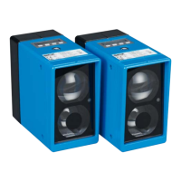
Fig. 3: ISD400 Pro structure
1 Threaded mounting hole M6
2 Center of optical axis, sender
3 Receive indicator
4 Center of optical axis, receiver
5 Ethernet female connector, M12, 4-pin, D-coded
6 Power supply male connector, M12, 4-pin, A-coded
7 Control element
8 Optical alignment aid
9 Alignment sight