Electrical connection
28 ©SICKAG•Subjecttochangewithoutnotice•8016441/2013-11-22
3
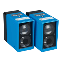
Fig. 10: Ideal laying –
Place cables in different cable channels
2
3
Fig. 11: Alternative laying – Separate cables with metallic separators
1 Cables very sensitive to interference (analog measuring cables)
2 Cables sensitive to interference (sensor cables, communication signals, bus
signals)
3 Cables which are a source of interference (control cables for inductive loads,
motor brakes)
4 Cables which are powerful sources of interference (output cables from fre-
quency inverters, welding system power supplies, power cables)
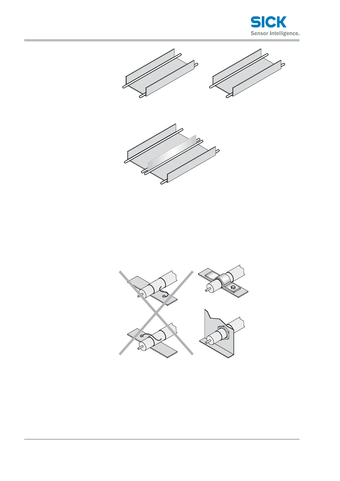
Fig. 12: Attach the screen using a short connection with a large surface area –
ground both ends
6.3 Connecting the ISD400 Pro electrically
1. Ensurethatthereisnovoltage.
2. ConnecttheISD400Proaccordingtotheconnectiondiagram.
→ SeePage29,Chapter6.4.