8014640/YWI5/2016-08-08 • Subject to change without notice • SICK AG • Waldkirch • Germany • www.sick.com 2LECTOR62X | SICK
Mounting device
1. Perform one of the following steps:
• Mount the device on a bracket supplied by the
customer using M5 screws. To do this, either
use the threaded mounting holes in the hous-
ing in pairs at the front or below or use the two
M5 sliding nuts in the lateral slots. Mounting
bracket no. 2042902 can be attached at the
bottom or on the sliding nuts. Screw the screws
no more than 5 mm into the blind tapped
holes. - Dimensional drawings, see “Setup
and function” on page 4.
• Attach the SICK bracket that has been or-
dered separately (e.g., mounting bracket no.
2042902) to the sensor using the two sliding
blocks. Refer to the “Mounting” chapter of the
Technical Information “Image-Based Code
Reader” Lector620.
Aligning the device plus reading window with
the code
Remember to consider the shape and alignment of
the eld of view in front of the device.
Fig. 1: Example for eld of view and reading eld, size
elongation depends on device
1. Working distance
2. Field of view (area at a certain working distance)
3. Reading eld (depth of eld)
Taking account of the working distance, depending
on the resolution
• Using the Auto-Setup function, the Lector620
automatically adjusts its focal position to suit the
working distance from the code.
• ECO variant: The focal position is set by entering
the working distance in SOPAS.
Variant-dependent visual and reading eld diagrams
can be found on the SICK product page in the web:
www.sick.com/lector62x
Maximum working distance with minimum resolution
Max. working distance
[mm]
Minimum resolution [mm]
50 0.10
105 0.20
160 0.30
220 0.40
270 0.50
330 0.60
380 0.70
Tab. 1: Example: Working distances of Professional variant
Allowing for reading angle
typical 20°
Fig. 2: Selection of the skew angle, depending on the
application
Tilt the device away from the plane that is per-
pendicular to the surface of the code to avoid as
many interfering reections as possible. Typically,
this angle will be between 10° and 20°. In the
case of codes created on metal, e.g., by dot peen-
ing, an angle of between 0° (bright eld light) and
45° (dark eld light) may be advisable.
Mounting the CDB connection module
These operating instructions describe the commis-
sioning of the CDB620-001 connection module. For
more information, see Operating instructions
“CDB620-001 connection module operating instruc-
tions” (no. 8012119). Alternatively, you can use the
CDB650-204 connection module.
Mount the connection module in the vicinity
of the device. If you are using the serial data
interface (RS-232), the maximum recommended
distance is 5 m.
Mount the connection module in such a way that
the Lector620 remains accessible at all times.
Step 2: Electrical installation
• The electrical installation must only be per-
formed by electrically qualied persons.
• Standard safety requirements must be met when
working on electrical systems.
• Electrical connections between the Lector620 and
other devices may only be created or disconnected
when there is no power to the system. Otherwise,
the Lector620 and devices may be damaged.
• When using connecting or extension cables with an
open end, make sure that bare wire ends are not
touching (risk of short-circuit when the supply volt-
age is switched on). Wires must be appropriately
insulated from each other.
• Wire cross-sections in the supply cable from the
customer's power system must be designed in ac-
cordance with the applicable standards.
• If the supply voltage for the Lector620 is not
supplied via the optional CDB620-001 connec-
tion module, the Lector620 must be protected by
a separate max. 2 A slow-blow fuse in the supply
circuit.
• All circuits connected to the Lector620 must be de-
signed as SELV circuits. The power supply or power
supply unit must satisfy SELV requirements in ac-
cordance with the currently applicable EN 60950-1.
(SELV = Safety Extra Low Voltage).
WARNING
Risk of injury and damage caused by electrical
current!
The Lector620 is designed to be operated in a system
with professional grounding of all connected devices
and mounting surfaces to the same ground potential.
Incorrect grounding of the Lector620 can result
in equipotential bonding currents between the
Lector620 and other grounded devices in the system.
This can lead to hazardous voltages being applied to
the metal housing, cause devices to malfunction or
sustain irreparable damage, and damage the cable
shield as a result of a heat increase, causing cables
to set alight.
Ensure that the ground potential is the same at all
grounding points.
If the cable insulation is damaged, disconnect the
supply voltage immediately and have the damage
repaired.
For measures for eliminating hazards, see Chapter
“Electrical installation”, in the Technical Informa-
tion “Image-based code readerLector620”.
1. Connect the communication interface of the
Lector620 to the PC (Ethernet or USB, depending
on model).
2. Supply power to the Lector620 according to the
type label.
- For an overview of all interfaces and connection
options, see “Overview of all interfaces and connec-
tion options” on page 7.
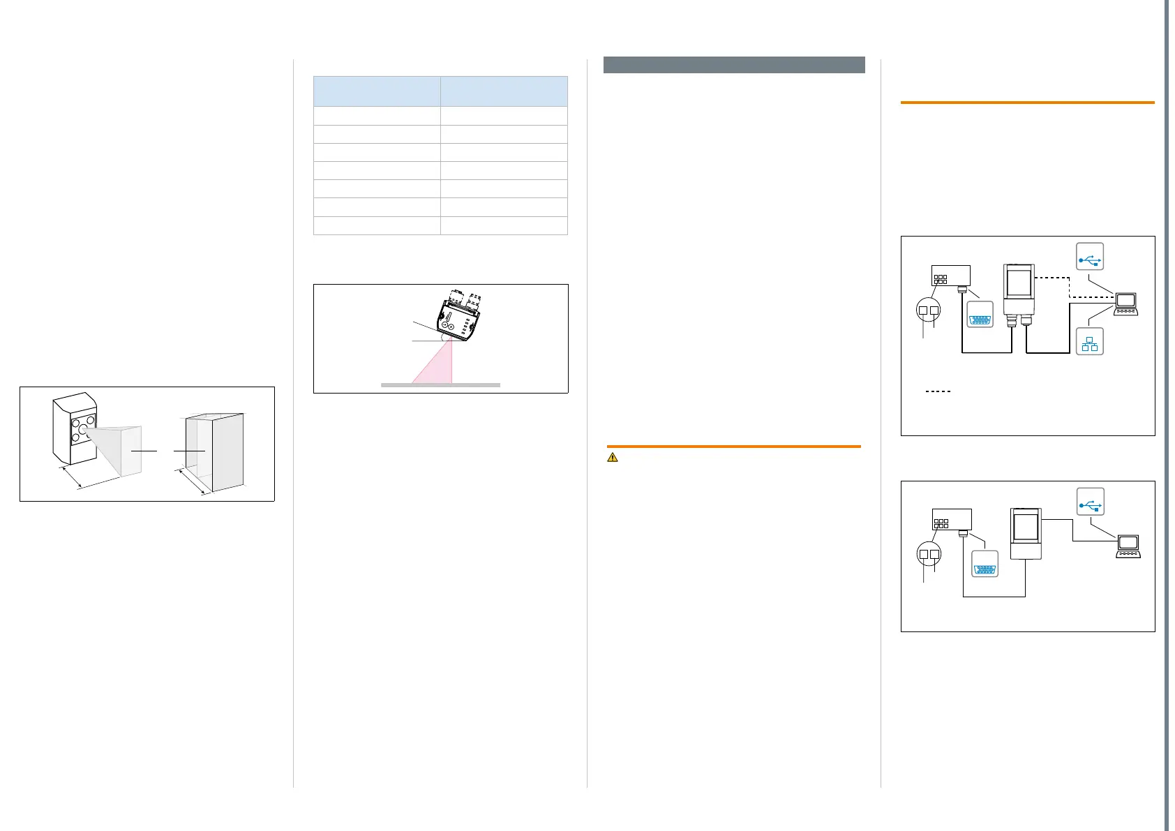
Connection module
CDB620-001
SOPASSOPAS
Lector
®
620
1
2
... 30 V
GND
Image
display
Diagnostcis
“Power”
“Ethernet”
“USB”
ICR620x-xxxYxx (Y = 5)
Swivel connector unit with 2 M12 cylindrical connectors
e.g. cable
no. 2055419
(2 m)
e.g. cable
no. 6034414
(2 m)
SerialSerial
...
...
alternative for configuration/image display,
e.g. cable no. 6036106 (2 m)
EthernetEthernet
USBUSB
Fig. 3: Connection block circuit diagram for Lector620
Professional, High Speed, DPM Plus and OCR with
swivel connector
Connection module
CDB620-001
SOPASSOPAS
Lector
®
620 ECO
1
2
V
GND
Image
display
Diagnostics
“Power”
SerialSerial
...
...
e.g. cable
no. 6036106
(2 m)
ICR620x-xxxYxx (Y = 0)
Cable with 15-pin D-Sub HD male connector
“USB”
USBUSB
Fig. 4: Connection block circuit diagram for Lector620 ECO
with cable outlet

 Loading...


