4.3 Assembly
Important information
DANGER
B
ypassing the protective device
Hazard due to lack of effectiveness of the protective device
b
Avoid incentives to manipulate the safety switch by taking at least one of the fol‐
lowing measures:
°
Cover the sensor and the actuator with additional equipment or protect them
against access.
°
If possible use permanent mounting methods for actuators (e.g., glue, safety
screws, or rivets).
Mounting location
b
S
elect the mounting location so that the sensor and actuator are accessible for
maintenance work and are protected against damage.
b
Select a mounting location that ensures the sensor is as far away from the door
hinge as possible.
b
If necessary, fit an additional stop for the moving protective device.
Distance
When several safety switches are mounted to the machine, they must be mounted at a
minimum distance to one another see "Mounting several safety switches", page 20.
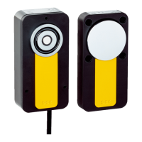
Alignment
The safety switch can be mounted in any alignment. When mounted horizontally, manip‐
ulation protection is increased by the anchor plate with rotating bearings. When
mounted horizontally, if the actuator is triggered by the movable physical guard, the
actuator is held by the magnet. As the anchor plate has rotating bearings, the gravita‐
tional force rotates the actuator surface away from the sensor surface and the OSSDs
go into the OFF state.
2 possible mounting methods
The sensor can be mounted in 2 ways:
•
Surface mounting. The sensor is mounted on the fixed part of the protective
device (e.g., door frame).
•
Flush mounting. The sensor is mounted in the fixed part of the protective device
(e.g., door frame). There must be a suitable recess in the mounting surface. The
thickness of the mounting surface must be between 1.5 mm and 3 mm.
Complementary information
Dimensional dr
awing of the recess for flush mounting see figure 17.
4.4 Integration into the electrical control
Switch-on commands that put the machine in a dangerous state may only be activated
when t
he protective device is closed. When the machine goes into a dangerous state, a
stop command must be triggered if the protective device is opened. Depending on the
safety concept, the signal is analyzed by safety relays or a safety controller, for example.
PROJECT PLANNING 4
8020169/ZJN1/2018-03-21 | SICK O P E R A T I N G I N S T R U C T I O N S | MLP1
13
Subject to change without notice