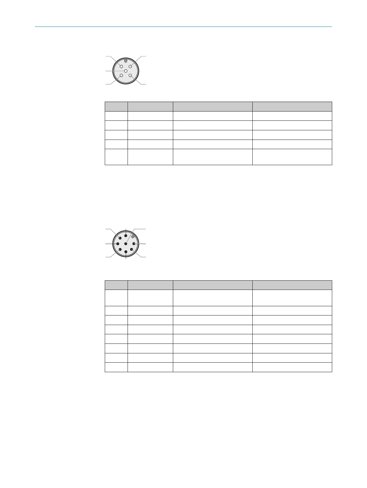
OUT device connection (female connector, M12, 5-pin, A-coded)
Table 7: OUT device connection pin assignment (female connector, M12, 5-pin, A-coded)
Pin Wire color
1)
Designation Description
1 Brown Out +24 V DC Safety switch voltage supply
2 White In 1 OSSD 1 input
3 Blue 0 V 0 V DC voltage supply
4 Black In 2 OSSD 2 input
5 Gray Magnet Output for magnet activation
24 V DC
1)
Applies to the extension cables recommended as accessories.
b
P
ay attention to tightness of the plug connectors.
6.4 Device connection (M12, 8-pin)
Device connection (male connector, M12, 8-pin, A-coded)
Table 8: Device connection pin assignment (male connector, M12, 8-pin, A-coded)
Pin Wire color
1)
Designation Description
1 White Aux Application diagnostic output
(no
t safe)
2 Brown +24 V DC Safety switch voltage supply
3 Green Magnet Magnet activation 24 V DC
4 Yellow In 2 OSSD 2 input
2)
5 Gray OSSD 1 OSSD 1 output
6 Pink OSSD 2 OSSD 2 output
7 Blue 0 V 0 V DC voltage supply
8 Red In 1 OSSD input 1
2)
1)
Applies to the extension cables recommended as accessories.
2)
When used as an individual safety switch or as the first safety switch in a cascade: Apply 24 V DC.
b
P
ay attention to tightness of the plug connector.
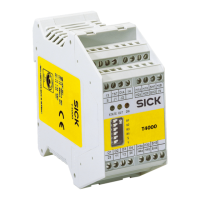
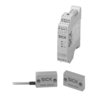
6.5 Connecting a cascade
A safety switch cascade can be created in different ways. Depending on the structure,
end connectors, T-connectors, and nodes are required for voltage supply (see "Acces‐
sories", page 41).
6 ELE
CTRICAL INSTALLATION
24
O P E R A T I N G I N S T R U C T I O N S | MLP1 8020169/ZJN1/2018-03-21 | SICK
Subject to change without notice