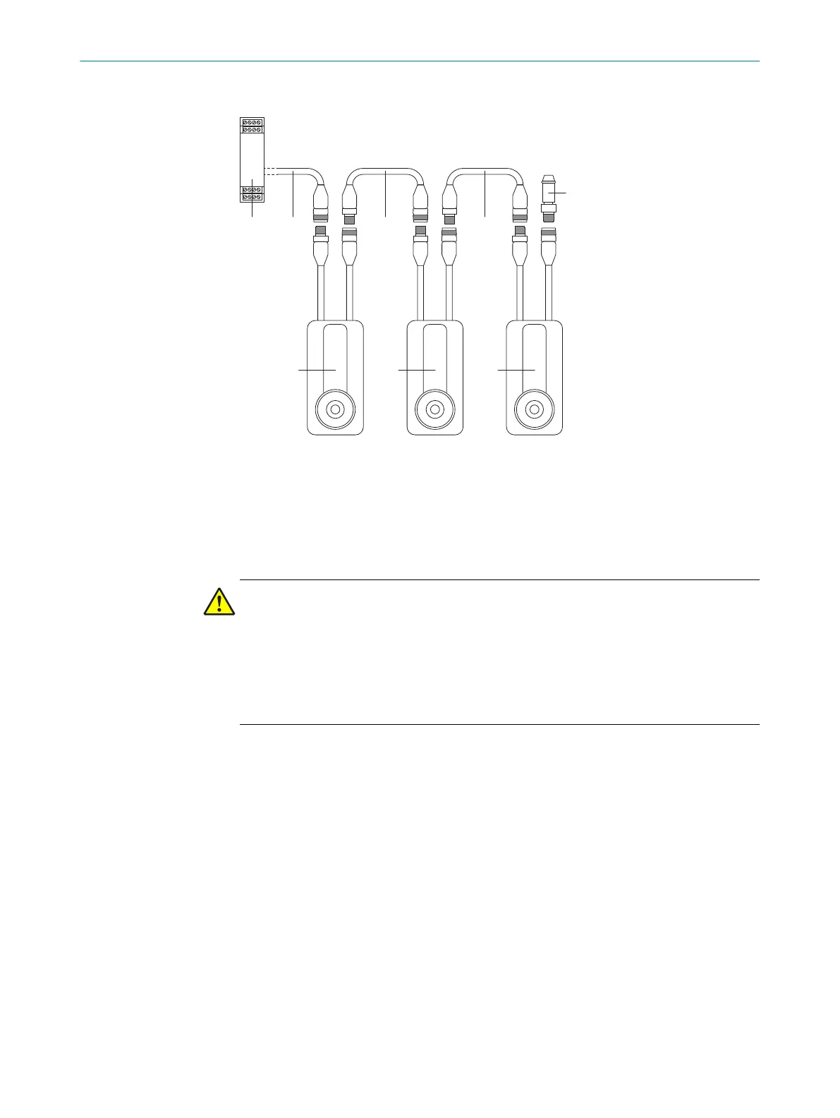
Connecting directly connected safety switches
Figure 11: Cascading several safety switches
1
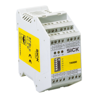
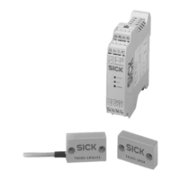
Safe evaluation unit
2
Connecting cable, M12, 5-pin
3
Connection cable, M12, 5-pin
4
End connector
5
MLP1 safety switch (2 × M12, 5-pin)
DANGER
B
ypassing the protective device
The dangerous state may not be stopped in the event of non-compliance.
b
If a cascade is created with directly connected safety switches, connecting cables
must be mounted so that a safety switch cannot be easily jumpered; e.g., cover
plug connectors or protect against access with additional means (e.g., protective
cover with disposable screws)
ELECTRICAL INSTALLATION 6
8020169/ZJN1/2018-03-21 | SICK O P E R A T I N G I N S T R U C T I O N S | MLP1
25
Subject to change without notice