6 Electrical installation
6.1 Notes on cULus
For use according to the requirements of UL 508, the following conditions must also be
me
t:
•
Voltage supply U
v
sensor secured with 2 A fuse
•
Voltage supply U
v
magnet secured with 2 A fuse
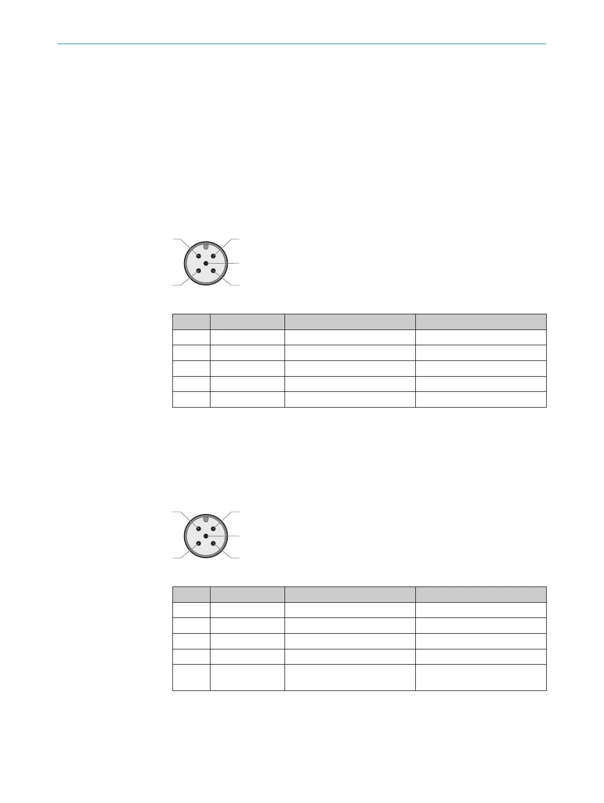
6.2 Device connection (M12, 5-pin)
Device connection (male connector, M12, 5-pin, A-coded)
Table 5: Device connection pin assignment (male connector, M12, 5-pin, A-coded)
Pin Wire color
1)
Designation Description
1 Brown +24 V DC Safety switch voltage supply
2 White OSSD 1 OSSD 1 output
3 Blue 0 V 0 V DC voltage supply
4 Black OSSD 2 OSSD 2 output
5 Gray Magnet Magnet activation 24 V DC
1)
Applies to the extension cables recommended as accessories.
b
P
ay attention to tightness of the plug connector.
6.3 Device connection (2 x M12, 5-pin)
IN device connection (male connector, M12, 5-pin, A-coded)
Table 6: IN device connection pin assignment (male connector, M12, 5-pin, A-coded)
Pin Wire color
1)
Designation Description
1 Brown In +24 V DC Safety switch voltage supply
2 White OSSD 1 OSSD 1 output
3 Blue 0 V 0 V DC voltage supply
4 Black OSSD 2 OSSD 2 output
5 Gray Magnet Input for magnet activation
24 V DC
1)
Applies to the extension cables recommended as accessories.
ELECTRICAL INSTALLATION 6
8020169/ZJN1/2018-03-21 | SICK O P E R A T I N G I N S T R U C T I O N S | MLP1
23
Subject to change without notice