As a result, maintenance intervals can be adapted to the actual maintenance require‐
ments. This results in reduced maintenance costs, higher machine availability, reduced
downtime/production loss costs, extended life cycles of machines and plants, and
increased production/product quality.
4.2.2 Status indicators
The LEDs indicate the current operational status of the Multi Physics Box. As shown in
figure 1, these light up the almost completely transparent seal to the outside at the
sides.
The different LED states are shown in table 1.
Table 1: LED states
LED Operational status
SIO mode active
(1Hz)
IO-Link communication
Alarm active
(2Hz)
Find device mode active
1
1
With the Find device mode, it is possible to clearly identify the Multi Physics Box via the LEDs.
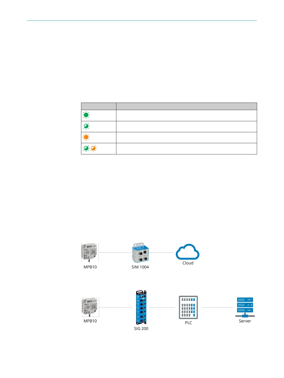
4.2.3 System architecture
The Multi Physics Box provides information for condition monitoring of machines and
processes.
For successful interpretation of conditions and incipient failures, ideally the threshold
of the condition change should be known or the sensor data should be analyzed. Both
on-premise and off-premise systems can be used for data analysis. Possible network
structures are listed in figure 3. An off-premise solution can be implemented via a
SIM1004 and via a secure SICK cloud connection using SICK LiveConnect. In the cloud,
services such as the Monitoring Box (www.sick.com/sick-monitoring-box) can be used.
Alternatively, the sensor can also be integrated into a PLC controller via an IO-Link
Master (e.g. SIG200) in order to save the data locally on a server.
Figure 3: Possible system architecture for data recording
PRODUCT DESCRIPTION
4
8028041/2022-08-16 | SICK O P E R A T I N G I N S T R U C T I O N S | MPB10
11
Subject to change without notice