7.2 Connections
7.2.1 Pin assignment/Connection diagram + wire colors
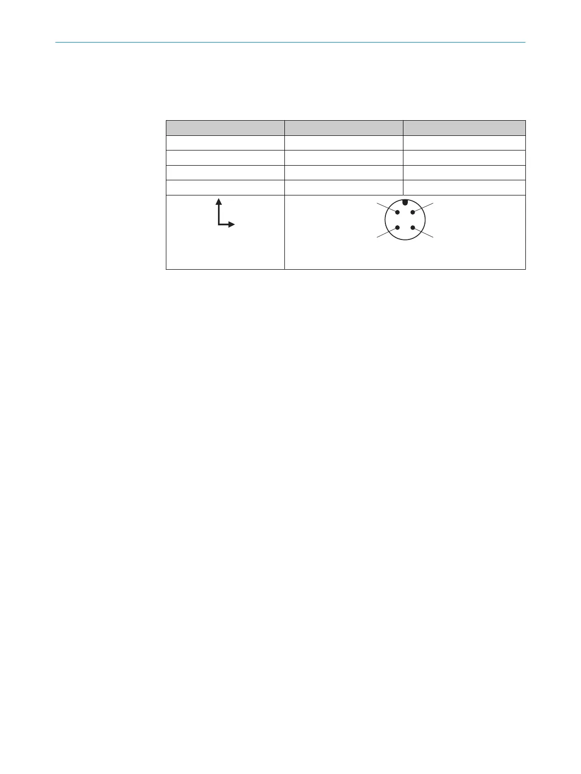
Table 8: Pin assignment for male connector, M12, A-coded, 4-pin
PIN Connection Pin assignment
1 BN + (L+)
2 WH MF
3 BU - (M)
4 BK Q/C
0.08mm
2
AWG 28
7.3 Connecting the supply voltage
The sensor must be connected to a voltage supply with the following properties:
•
Supply voltage DC 10V ... 30V (SELV according to currently valid standards)
•
Power source with at least 5W power
Protecting the supply cables
To ensure protection against short-circuits/overload in the customer’s supply cables,
the wire cross-sections used must be appropriately selected and protected.
7 ELECTRICAL INSTALLATION
26
O P E R A T I N G I N S T R U C T I O N S | MPB10 8028041/2022-08-16 | SICK
Subject to change without notice