°
Group 1: Cables very sensitive to interference, such as analog measuring
cables
°
Group 2: Cables sensitive to interference, such as sensor cables, communi‐
cation signals, bus signals
°
Group 3: Cables which are a source of interference, such as control cables
for inductive loads, motor brakes
°
Group 4: Cables which are powerful sources of interference, such as out‐
put cables from frequency inverters, welding system power supplies, power
cables
b
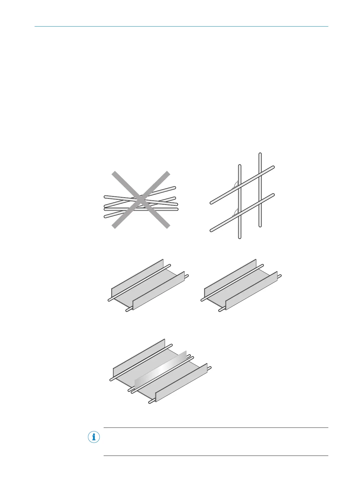
Cables in groups 1, 2 and 3, 4 must be crossed at right angles, see figure 11.
b
Cables in groups 1, 2 and 3, 4 must be routed in different cable ducts or
metallic separators must be used, see figure 12 and see figure 13. This
applies particularly where cables of devices with a high level of radiated
emission, such as frequency converters, are laid parallel to sensor cables.
Figure 11: Cross cables at right angles
Figure 12: Ideal laying – Place cables in different cable ducts
Figure 13: Alternative laying – Separate cables with metallic separators
NOTE
Prevent equipotential bonding currents via the cable shield with a suitable earthing
method, see "Safety", page 24.
ELECTRICAL INSTALLATION 7
8028041/2022-08-16 | SICK O P E R A T I N G I N S T R U C T I O N S | MPB10
25
Subject to change without notice