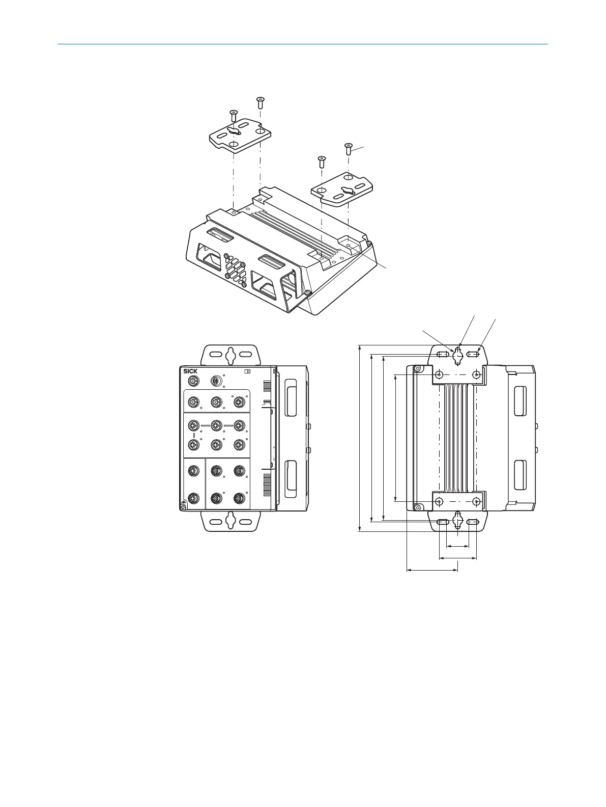
Mounting the device in a vertically suspended or horizontal position using adapter
plates
SIM2x00
POWER
SERIAL
SENSOR
FIELDBUS ETHERNET
INC CAN
S2S1 S3
S5S4 S6
1
1
2
3
4
P1
P2
1
2
3
4
P1
P2
P1 2
3P2 4
I/0
7
1
2
8
3
4
5
6
7
1
2
8
3
4
5
6
7
1
2
8
3
4
5
6
POWER IN1
POWER IN2
Dev RDY
Sys RDY
Result
Funct 1
Funct 2
Remote
Dev RDY
Sys RDY
Result
Funct 1
Funct 2
Remote
BF/ERR/
NS
Mode Micro-SD USB
SF/RUN/
MS
BF/ERR/
NS
SF/RUN/
MS
Pwr/Act
Pwr/Act Pwr/Act
Pwr/Act
IO-Link IO-Link
IO-Link
Pwr/Act
Pwr/Act Pwr/Act
Pwr/Act
Pwr/Act
PoE PoE
PoE PoE
Pwr/Act
Term
Link
Act
Link
Act
Link
Act
Link
Act
Link
Act
Link
Act
Link
Act
Link
Act
Link
Act
Link
Act
Link
Act
Link
Act
1
2
170
220
225
250
R 3,2
R 3,2
R 6,5
50
69
30
1. Attach the adapter plates to the device using two hexagon socket head cap screws
(A/F 3) on each.
2. Mount the device with adapter plates at the mounting location (vertically sus‐
pended or horizontal position).
°
for suspended mounting, use the individual screw slots on the adapter
plates.
°
for horizontal mounting, use at least 2 of the 4 screw slots on the plates.
3. Mark the mounting holes.
4. Proceed to drill the mounting holes.
5. Mount the device with adapter plates using at least two screws.
5
MOUNTING
18
O P E R A T I N G I N S T R U C T I O N S | SIM2000 8023297//2021-06-22 | SICK
Subject to change without notice
 Loading...


