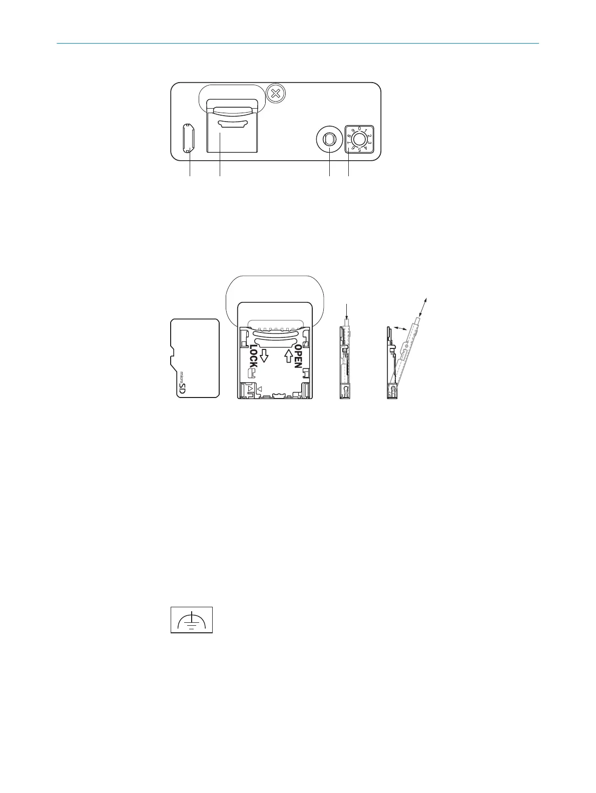
Connections/control elements under the servicing panel
1
USB connection (Micro-B, for configuration/diagnostics/firmware update)
2
microSD card slot
3
Function button
4
Function selector switch (configurable by SensorApp)
Installing/removing a micro-SD card
1. Open the servicing panel by removing the two screws.
2. To install an SD card, gently press the SD card tray to release (1) and then open it
(2).
b
Insert the card with the contact side facing down (3).
b
Close the SD card tray and lock it.
3. To remove the card, release the card tray (1) and open it (2).
b
Pull out the SD card (3).
b
Close the SD card tray and lock it.
4. Close the service cover and tighten the two screws.
6.5
Functional earth connection
Figure 1: Alternative FE connection
The functional earth (FE) is connected either via the housing or via an FE connection
with cable lug.
Alternative FE connection
Screw connection of the alternative functional earth connection
•
Screw: M4 x 15
ELECTRICAL INSTALLATION 6
8023297//2021-06-22 | SICK O P E R A T I N G I N S T R U C T I O N S | SIM2000
21
Subject to change without notice
 Loading...


