Table 6: Fieldbus connections
Pin Signal Function
1 TD+ (TX1_P) Transmit data +
2 RD+ (RX1_P) Receive data +
3 TD- (TX1_N) Transmit data -
4 RD- (RX1_N) Receive data -
Housing - Screen
Additional notes:
•
Designed for line topology
•
Data transmission rates: 10/100 Mbit/s
•
PROFINET and EtherNet/IP support,
EtherCAT
®
* under development
* EtherCAT
®
is a registered trademark and patented technology licensed by Beckhoff
Automation GmbH, Germany.
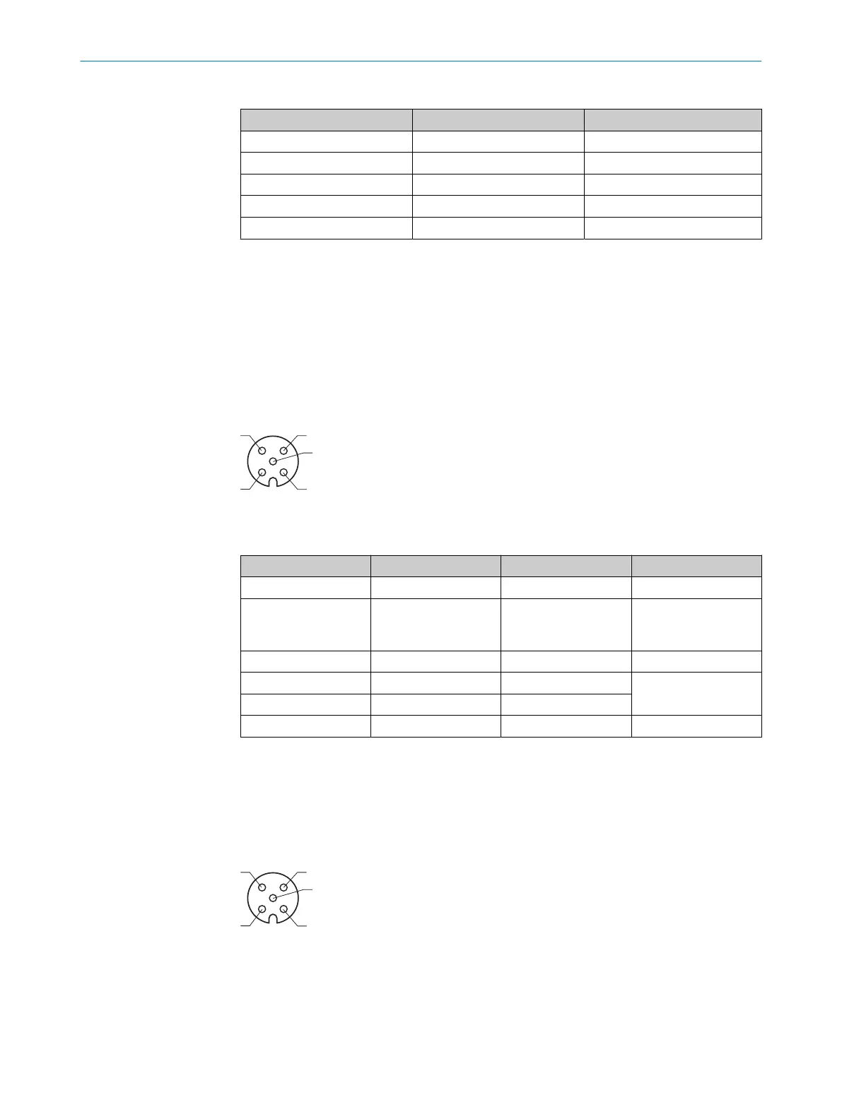
6.6.6 CAN
Figure 7: CAN pin assignment, M12 – 5-pin A-coded, female
Table 7: CAN connection
PIN Signal Function Factory settings
1 - Screen -
2 + 24 V Supply voltage for
peripherals, configura‐
ble
Deactivated
3 GND Ground -
4 CAN_H CAN HIGH
Termination deacti‐
vated
*)
5 CAN_L CAN LOW
Housing - Screen -
*)
Termination controllable via app
Additional notes
•
Max. 3.2 A output for supply voltage connections (compliant with LPS)
6.6.7 Sensor 1-4
Figure 8: SENSOR 1-4 pin assignment, M12 - 5-pin A-coded, female
ELECTRICAL INSTALLATION 6
8023297//2021-06-22 | SICK O P E R A T I N G I N S T R U C T I O N S | SIM2000
25
Subject to change without notice
 Loading...


