PIN Signal Function Factory settings
3 GND Ground -
4 Input 1 / output 1 Configurable digital
input/output
All IO connections con‐
figured as inputs
5 Input 2 / Output 2 Configurable digital
input/output
All IO connections con‐
figured as inputs
Housing - Screen -
Additional notes
•
S6 is factory configured for connecting and regulating the device fan, but can also
be used as a SENSOR port like S5, see "Preparatory commissioning", page 29.
•
The digital inputs and outputs are only switchable if the supply voltage is activated
on pin1, or +24 V is externally applied to pin1. A ground connection on Pin3 is
required in both cases.
Digital outputs:
°
Max. output 100 mA
°
Min. high output logic level: VCC - 3 V
°
Max. low output logic level: 3 V
°
Push-pull switch
°
Max. IO output frequency: 30 kHz
Digital inputs:
°
Min. high input logic level: 12 V
°
Max. low input logic level: 4 V
°
Max. input frequency for input3: 10 kHz
°
Max. IO input frequency: 30 kHz
•
Max. 2.5 A output for supply voltage connections S5 to S6 (compliant with LPS). To
enable voltage supply to the peripherals, both voltage supply strands from POWER
MAIN must be connected to 24 V.
•
HTL encoders use push-pull switches and can therefore be connected via digital
inputs.
Recommendation when using S5 to S6 for illumination:
Short flash times can be achieved using two alternative modes:
1. Power Strobe Mode: when using the “Connector.Power.Gate” API (see the API
documentation)
2. Signal Strobe Mode: when using pin 4 or pin 5 as a switching output signal with a
constant supply voltage on pin 1 (only for illumination units with signal strobe)
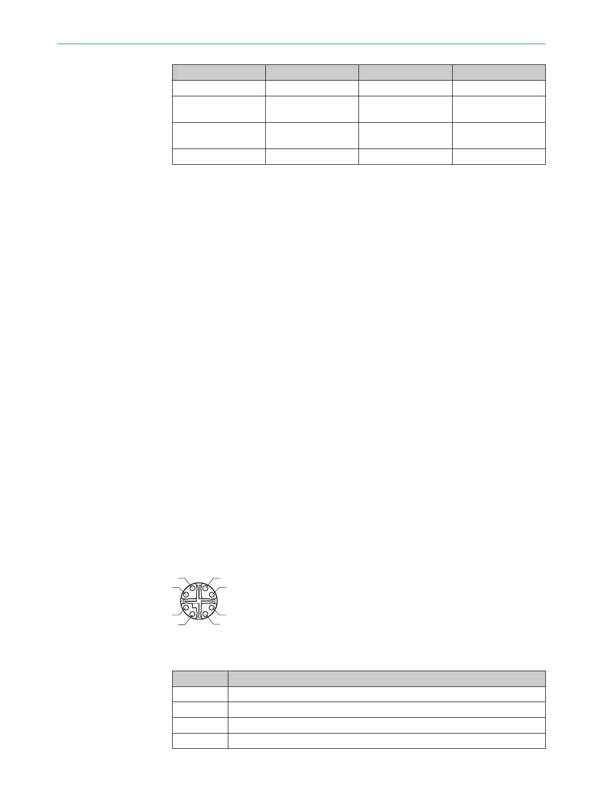
6.6.9 ETHERNET
Figure 10: Ethernet pin assignment, M12 – 8-pin X-coded, female
Table 10: Ethernet 1-4 connections
PIN Function
1 D1+ (PoE supply voltage)
2 D1- (PoE supply voltage)
3 D2+ (PoE ground)
4 D2- (PoE ground)
ELECTRICAL INSTALLATION 6
8023297//2021-06-22 | SICK O P E R A T I N G I N S T R U C T I O N S | SIM2000
27
Subject to change without notice
 Loading...


