Operating Instructions | SICK 59
Operating Instructions PAC50
8017612/ZAB1/2017-02-14 | PAC50
Subject to change without notice
5 Installation/Mechanical connection
5.1 Installation on the mounting rail
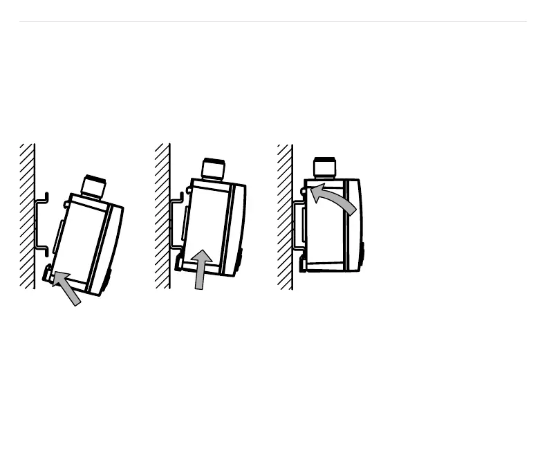
The PAC50 pressure switch has an integrated xing mechanism for installing on a mounting rail according to
DIN EN 60715 – 35 mm x 15 mm/7.5 mm.
•
To install the PAC50, position the lower xing guide on the mounting rail (see Figure 7 1) and tilt the
PAC50 up until it locks into place (see Figure 7 2 and 3).
•
To remove the PAC50 from the mounting rail, pull the xing clip down and tilt the PAC50 up and away from
the mounting rail.
Figure 7: Installation on the mounting rail
5.2 Installation with a switch panel mounting set
To install in a switch panel, use the switch panel mounting set, which is available as an accessory (see
Figure 8). The maximum switch panel thickness is 5 mm. Figure 9 shows the dimensions of the cut-out
section in the switch panel.