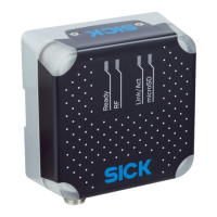
3.2 Product characteristics
3.2.1 Device view
92 (
3.62
)
1
9
8
94 (
3.70
)
106.4 (
4.19
)
Ready
RF
Link/Act
microSD
40 (
1.57
)
16
(
0.63
)
36 (
1.42
)
â
80 (
3.15
) 38 (
1.50
)
12
(
0.47
)
71 (
2.80
)
40 (
1.57
)
5
(
0.20
)
6.4
(
0.25
)
17.5
(
0.69
)
78.8 (
3.10
)
1 3 2
91°
3 (
0.12
)
11.5 (
0.45
)
9.5 (
0.37
)
2
1
4
3
2 3
4 5
ß
á à
6
7
17.5
(
0.69
)
Figure 3: RFU61x-106xx: Structure and dimensions, unit: mm (inch), decimal separator: period
1
Connection 1: Power (male connector, M12, 4-pin, A-coded)
2
Connection 3: Trigger (female connector, M8, 4-pin, coded)
3
Connection 2: PoE (female connector, M12, 8-pin, X-coded)
4
Slot for microSD memory card
5
“USB” connection (female connector, 5-pin, Micro B type). The USB interface must only be
used temporarily as a servicing interface!
6
Side type label
7
Optics cover with integrated antenna
8
4 x multi-colored LED (status)
9
4 x multi-color LED (process feedback)
ß
2 x M5 threaded mounting holes, 6 mm deep, for attaching the mounting straps
à
2 x M5 blind tapped holes, 7 mm deep, for alternative mounting of the device
á
type label with integrated pressure compensation membrane
â
2 x screw (M2,5 socket screw), captive, for side cover
3.2.2 Working range of the antenna
Sensing range of the reading and writing field
The environment influences the UHF field of the integrated antenna, making it impossi‐
ble to provide a “clear” demarcation of the sensing range.
PRODUCT DESCRIPTION 3
8024536//2019-08-30 | SICK O P E R A T I N G I N S T R U C T I O N S | RFU61x
15
Subject to change without notice

 Loading...