•
All cables connected to the device must be clamped. Electrical M12 or M8 con‐
nections that are not being used must be sealed with screw-on protective ele‐
ments as in the delivery condition. Protective caps for male connectors or protec‐
tive plugs for female connectors.
•
When operating the device at the lower limit of the permissible ambient tempera‐
ture range (see "Technical data", page 61), do not expose the device to strong air
flows (e.g. ventilation system, wind).
6.5.2 Behavior of the device when switched on
After application of the supply voltage and initialization, the device can immediately be
addressed by the SOPAS ET configuration software.
Table 10: Behavior of the device when switched on at low temperatures
Internal temperature of
housing
Behavior
Below –25 °C “Ready” LED continuously flashes orange.
Device is not operational because –25 °C is below the specified
minimum limit value.
-25 °C ... -20 °C “Ready” LED continuously flashes green (warm-up phase).
Device is not operational (communication channel still disabled)
until the internal temperature has increased to –20 °C as a result
of the heat generated by the electronics. Duration approx. 2 min.
From –20 °C “Ready” LED permanently lights up green.
The device has started regular operation.
1)
For Firmware Version V2.02
Once the supply voltage has been applied, the device uses integrated temperature sen‐
sors to measure its internal temperature. This is performed by the device while booting.
6.6 Installation steps
6.6.1 Wiring of the device for Quickstart
NOTE
The numbering of the data interfaces (Aux 1, etc.) in the following block diagrams pro‐
vides a better overview, but is not shown in the SOPAS ET configuration software.
Connection type: power and Ethernet
SOPAS ETSOPAS ET
PC
"Ethernet (Host 1/Aux 1)"
USBUSB
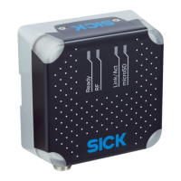
RFU61x-
106xx
Cable 3
5
"Power"
EthernetEthernet
"USB" (Aux 2), for temporary use only 4
Configuration
Reading result
display
Transponder
access
Reading
diagnostics
Ready
RF
Link/Act
microSD
Cable 6
V
S
2
Trigger
sensor
1
Figure 21: Commissioning: connection block diagram of the RFU61x-106xx (power and Ethernet)
1
Trigger sensor for external read cycle (optional)
2
Supply voltage V
S
3
Adapter cable (male connector, USB, Micro-B type/male connector, USB, type A)
ELECTRICAL INSTALLATION 6
8024536//2019-08-30 | SICK O P E R A T I N G I N S T R U C T I O N S | RFU61x
41
Subject to change without notice

 Loading...