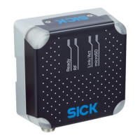
12.2 Interfaces
Table 20: Technical data for RFU61x: Interfaces
RFU61x-106xx
Ethernet
•
Protocol: TCP/IP
•
Function: host (data output of the read result)
•
Function: Aux (service)
1)
•
Data transmission rate 10/100 Mbit/s
•
Services: DHCP, NTP, HTTP/HTTPS
PROFINET
•
Protocol: PROFINET
•
Function: host (data output of read result), PROFINET Single
Port
2)
•
Data transmission rate 10/100 Mbit/s
EtherNet/IP™
•
Protocol: EtherNet/IP™
•
Function: host (data output of the read result)
•
Data transmission rate 10/100 Mbit/s
USB 2.0
3)
•
Function: Aux (service)
1)
Digital input
•
Version: physical, switching
•
V
in
4)
= max. 30 V, I
in
5)
= max. 5 mA. V
S Trigger
6)
= V
S
, I
S trigger
7)
=
max. 40 mA
•
Debounce time: adjustable
8)
•
A corresponding trigger sensor (e.g. GL 6) can be connected
directly
Optical indicators
•
4 RGB LEDs (status indicators) on front top
•
4 x RGB LEDs (process feedback) in the four corners of the
antenna cover. Display function can be set with pre-defined
color assignment
8)
.
Configuration SOPAS ET configuration software, CoLa commands (telegrams),
web server, fieldbus controller (PLC) with additional support by
SICK function blocks
Programming Application-specific programming with SICK AppStudio
9)
develop‐
ment environment.
You can find further information on the Internet at:
www.sick.com/SICK_AppStudio
1)
For example: Configuration, diagnosis, transponder access or display of the read result.
2)
Function blocks for PLC types from different manufacturers are available online at: www.sick.com/
RFU61x.
3)
The USB interface must only be used temporarily as a servicing interface!
4)
Input voltage.
5)
Input current.
6)
Supply voltage for external trigger sensor
7)
Supply current for external trigger sensor
8)
For example using the SOPAS ET configuration software.
9)
This functionality can be unlocked with the SDK6U SD card. Available online at: www.sick.com
12.3 Mechanics and electronics
Table 21: Technical data for RFU61x: Mechanics/electronics
RFU61x-106xx
Electrical connection
•
Connection 1: male connector, M12, 4-pin, A-coded
•
Connection 2: female connector, M12, 8-pin, X-coded
•
Connection 3: female connector, M8, 4-pin, coded
•
USB interface: female connector, 5-pin, Micro B type
12 TECHNICAL DATA
62
O P E R A T I N G I N S T R U C T I O N S | RFU61x 8024536//2019-08-30 | SICK
Subject to change without notice

 Loading...