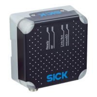
Table 8: Pin assignment of the “PoE” connection
Pin Signal Function
1 TD+ Sender+
2 TD– Sender–
3 RD+ Receiver+
4 RD– Receiver–
5 PoE– Supply voltage-
6 PoE– Supply voltage-
7 PoE+ Supply voltage+
8 PoE+ Supply voltage+
6.4.3 Connection of external trigger sensor
6.4.3.1 Connection 3: “Trigger”
Figure 20: Female connector, M8, 4-pin, coded
Table 9: Pin assignment of the “Trigger” connection
Pin Signal Function
1 V
S trigger
Supply voltage for external trigger sensor
2 N.c. –
3 GND Functional ground
4 Sensor 1 Digital input
6.5 Instructions for electrical installation when the ambient temperature can fall below
0 °C
NOTE
For mounting instructions, see "Instructions for mounting the device when the ambient
temperature can fall below 0 °C", page 25
All device variants can also be operated at low ambient temperatures. For details, see
"Technical data", page 61
6.5.1 Prerequisites
•
Required supply voltage: see "Supply voltage", page 43
•
Use SICK standard cables for the specified ambient temperature range, see
°
www.sick.com/RFU61x
•
Do not operate the device at ambient temperatures below 0 °C when mounting or
connection work is being carried out.
•
Perform all connection work only in the ambient temperature range 0 °C to
+50 °C. Secure the connecting cables.
•
The joint side cover for the USB interface and the memory card slot is screwed
tightly onto the device.
6 ELECTRICAL INSTALLATION
40
O P E R A T I N G I N S T R U C T I O N S | RFU61x 8024536//2019-08-30 | SICK
Subject to change without notice

 Loading...