■
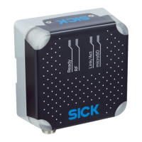
Fasten the device using the 2 fastening clamps supplied or the 2 M5 threaded
mounting holes.
■
Mount the device where they will not be exposed to shocks or vibration.
5.2.2 Instructions for mounting the device when the ambient temperature can fall below 0 °C
The device can also be operated at low ambient temperatures. For details, see "Techni‐
cal data", page 61.
NOTE
For the electrical installation procedure, see "Instructions for electrical installation when
the ambient temperature can fall below 0 °C", page 40
NOTICE
Operating the device at the lower limit of the permissible ambient temperature range
The ensure the device can produce the required heating power, do not expose the
device to strong air flows (e.g. from a ventilation system).
b
If necessary, take appropriate measures to shield the device from air flows.
NOTICE
If the ambient temperature is below 0 °C, please note:
•
Do not move the connecting cables to the device
5.2.3 Auxiliary equipment required
■
If the two fastening clamps of the enclosed mounting kit do not cover the mount‐
ing situation of the application, the customer must provide a suitable mounting
device (bracket). The bracket requires sufficient load-bearing capacity, see "Tech‐
nical data", page 61 and dimensions adapted to the device, see "Device view",
page 15.
■
2 M5 screws to attach the device to a bracket if the supplied mounting straps are
not used.
NOTE
The screws are for mounting the device on mounting equipment (bracket) supplied
by the user. The screw length required depends on the mounting base (wall thick‐
ness of the bracket).
When using an optional SICK bracket, the screws for mounting the device on the
bracket are included in the scope of delivery.
NOTICE
Risk of damage to the device!
Screws that are not suitable for the length of the threaded mounting holes can
damage the device.
•
M5 threaded mounting hole for mounting from the rear: screw in screws to a
maximum depth of 7 mm!
•
M5 threaded mounting holes for mounting strap: Do not exceed the maxi‐
mum screw-in depth of 6 mm!
■
Tool and tape measure
MOUNTING
5
8024536//2019-08-30 | SICK O P E R A T I N G I N S T R U C T I O N S | RFU61x
25
Subject to change without notice

 Loading...