4
USB, alternative to Ethernet Aux port. The USB interface must only be used temporarily as
a servicing interface!
5
Configuration with SOPAS ET, prepared representation of the read result, transponder
access or reading diagnostics
6
Adapter cable (male connector, M12, 8-pin, X-coded/male connector, RJ-45, 8-pin)
Procedure:
1.
Connect the communication interface (e.g. Ethernet) of the device directly 6to the
PC using a suitable cable.
2. Connect the “Power” connection (male connector, M12, 4-pin, A-coded) to the
power source using a suitable cable.
Connection type: Power over Ethernet
SOPAS ETSOPAS ET
PC
"Ethernet (Aux 1)"
USBUSB
PoE Switch
(Endspan)
...
DC 48 V/57 V
PSE
**)
PD
*)
RFU61x-
106xx
*) PD = Powered Devices 6 **) PSE = Power Sourcing Equipment 5
"Ethernet"
Cable 2
4
EthernetEthernet
"USB" (Aux 2), for temporary use only 3
Configuration
Reading result
display
Transponder
access
Reading
diagnostics
PD
*)
EthernetEthernet
"Ethernet (Host 1/Aux 1)/Power"
Cable 7
Ready
RF
Link/Act
microSD
Trigger
sensor
1
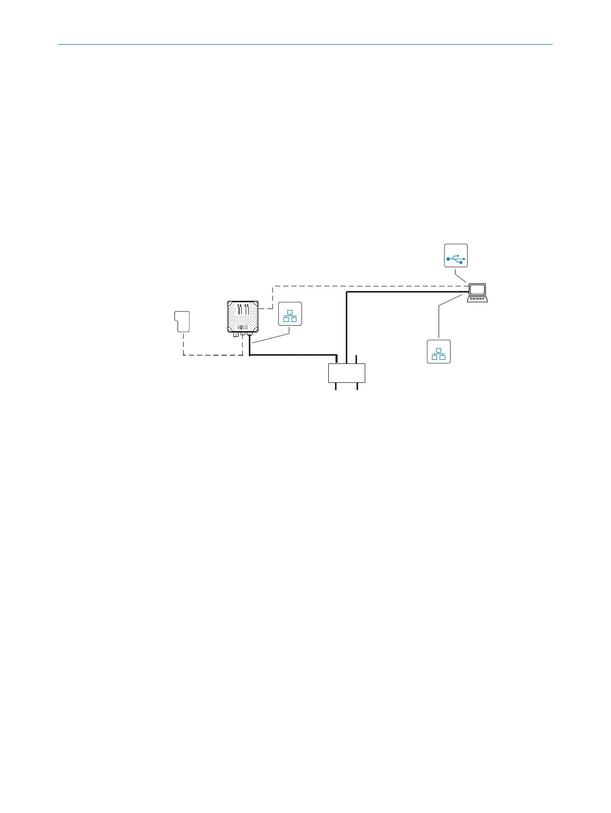
Figure 22: Initial commissioning: connection block diagram RFU61x-106xx (Power over Ethernet)
1
Trigger sensor for external read cycle (optional)
2
Adapter cable (male connector, USB, Micro-B type/male connector, USB, type A)
3
USB, alternative to Ethernet Aux port. The USB interface must only be used temporarily as
a servicing interface!
4
Configuration with SOPAS ET, prepared representation of the read result, transponder
access or reading diagnostics
5
PSE = Energy source
6
PD = Energy consumer
7
Adapter cable (male connector, M12, 8-pin, X-coded/male connector, RJ-45, 8-pin)
Procedure:
b
Connect the PoE communication interface of the device to the PoE switch using a
suitable adapter cable 7.
General for both connection types
1. If necessary, connect the trigger sensor for an external read cycle, such as a pho‐
toelectric sensor, to the “Trigger” connection.
The device offers the “Quickstart” operating mode for demonstrating its operating
principle. In this mode, the device automatically triggers a cyclic reading. The oper‐
ating mode can, for example, be started and terminated with the SOPAS ET config‐
uration software.
6 ELECTRICAL INSTALLATION
42
O P E R A T I N G I N S T R U C T I O N S | RFU61x 8024536//2019-08-30 | SICK
Subject to change without notice

 Loading...